


21
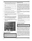
Gas Supply Connection
The heater must be isolated from the gas supply pip-
ing system by closing the manual shut-off valve during
any pressure testing of the gas supply piping system
at test pressures equal to or less than 1/2 psi (3.45
kPa). Relieve test pressure in the gas supply line prior
to reconnecting the heater and its manual shut-off
valve to the gas supply line. FAILURE TO FOLLOW
THIS PROCEDURE MAY DAMAGE THE GAS
VALVES. Over pressurized gas valves are not cov-
ered by warranty. The heater and its gas connections
shall be leak-tested before placing the appliance in
operation. Use soapy water for leak test. DO NOT use
an open flame.
CAUTION: The heater must be disconnected from
the gas supply during any pressure testing of the gas
supply system at test pressures in excess of 1/2 psi
(3.45 kPa).
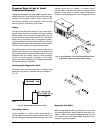
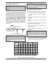
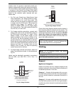
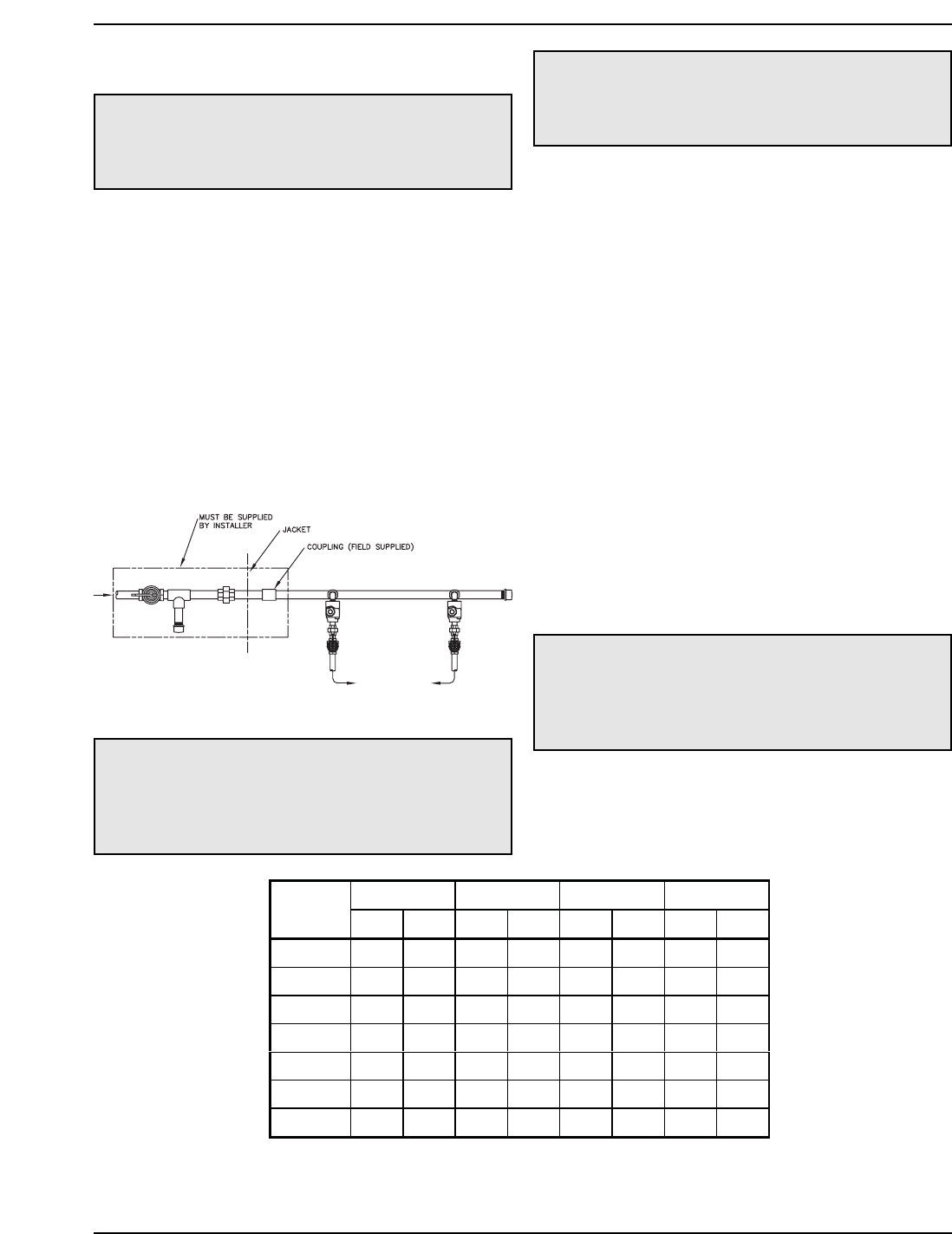
Fig. 16: Gas Supply Connection
CAUTION: Do not use Teflon tape on gas line pipe
thread. A pipe compound rated for use with natural
and propane gases is recommended. Apply sparing-
ly only on male pipe ends, leaving the two end
threads bare.
CAUTION: Support gas supply piping with hang-
ers, not by the heater or its accessories. Make sure
the gas piping is protected from physical damage
and freezing, where required.
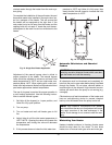
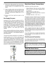
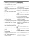
Reversing Gas Supply Connection
Reversing the standard fuel connection from the left-
hand to the right-hand side is a simple field operation.
1. Disconnect all electrical power from the heater (if
applicable).
2. Disconnect the main gas pipe from the heater (if
applicable).
3. Remove the left and right front panels from the
heater.
4. Locate the main gas line that traverses across the
heater above the manifold risers.
5. Remove the pipe cap from the right-hand end of
the main gas line.
6. Reinstall the pipe cap on the left-hand end of the
main gas line.
7. Remove plastic cap from the right-hand side panel
and reinstall into the standard main gas opening
located on the left-hand side of the heater.
CAUTION: Do not use Teflon tape on main gas line
pipe thread. A pipe compound rated for natural and
propane gases is recommended. Apply sparingly
only on male pipe ends leaving the two end threads
bare.
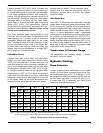
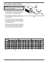
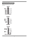
2” 2-1/2” 3” 4”
Model
No.
NPNPNPNP
992A 120 300 300 -- -- -- -- --
1262A 75 180 170 325 560 -- -- --
1532A 50 120 125 250 400 -- -- --
1802A 40 100 100 225 340 -- -- --
2002A 30 80 75 175 260 -- -- --
2072A 30 80 75 175 260 -- -- --
2342A 20 55 55 135 160 400 600 --
Natural gas – 1,000 BTU per ft
3
, .60 specific gravity at 0.5 in. WC pressure drop
Propane gas – 2,500 BTU per ft
3
, 1.53 specific gravity at 0.6 in. WC pressure
drop
Table I: Maximum Equivalent Pipe Length