


SECTION D: Start up
44
Safety Inspection
1. Check all thermostats and high limit settings.
2. During the following safety checks leave manome-
ters hooked up, check and record.
3. If other gas-fired appliances in the room are on the
same gas main, check all pressures on the MVB
with all other equipment running.
4. Check thermostats for ON-OFF operation.
5. Check high limits for ON-OFF operation.
6. While in operation, check flow switch operation
7. Check the low gas pressure switch (if provided).
(For proper adjustment, use the attached manome-
ters, if available, to set pressure. The scales on the
switch are approximate only.) Low gas pressure
switch (if provided) must be set at 3.0 in. WC for
natural gas and propane gas.
8. Make sure that the high gas pressure switch (op-
tional) is set to 3.0 in. WC for both natural gas and
propane gas.
Follow-Up
Safety checks must be recorded as performed.
Turn heater on. After main burner ignition:
1. Check manometer for proper readings.
2. Cycle heater several times and re-check readings.
3. Remove all manometers and replace caps and
screws.
4. Check for gas leaks one more time.
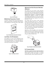
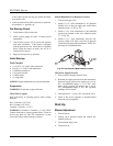
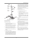
Leak Test Procedure: Dual-Seat Gas
Valve
Proper leak testing requires three pressure test points in
the gas train.
Remove the access panel on the rear of the heater to
access the gas valve for this test. Test point A is a
bleedle valve located upstream of the combination gas
valve on the supply manifold.
Test point B is a bleedle valve located between the two
automatic gas valve seats.
Test point C is a bleedle valve located downstream of
both automatic gas valve seats and upstream of the
manual valve. Refer to Fig. 40.
These tests are to be conducted with the electrical
power to the heater turned OFF.
1. Manually close the downstream leak test valve.
2. Open the bleedle valve at test point A and connect
a manometer to it. Verify that there is gas pressure
and that it is within the proper range (NOTE: must
not exceed 14.0 in. WC).
3. Open test point B and connect a rubber tube to it.
Connect the other end of the tube to a manometer
and look for a build-up of pressure. Increasing
pressure indicates a leaking gas valve which must
be replaced.
4. Next, close the upstream manual gas valve (field
supplied) and remove the manometers from the
bleedle valves in test point A and test point B.
Connect a rubber tube from the test point A
bleedle valve to the test point B bleedle valve and
open the upstream manual gas valve. Make sure
that test point A & B bleedle valves have been
opened so as to allow gas to flow. This will bring
gas pressure to the second valve seat.
5. Open the bleedle valve at test point C and connect
a second rubber tube to it. Connect the other end
of the tube to a manometer and look for a build-up
of pressure. Increasing pressure indicates a leaking
gas valve which must be replaced.
6. Remove rubber tube and manometers. Close each
test point bleedle valve as the tubes are removed.
7. After no leakage has been verified at all valve
seats and test valves, open downstream leak test
valve and restore electrical power to the heater.