


SECTION C: Installation
34
When the 24 VAC signal is sent from the flow
switch to P4-9, the same signal then de-energizes
the coil of the time delay relay to remove a heat
demand from the modulating temperature control
and restart the ignition sequence after the five-
second time delay.
Upon ignition lockout, the module energizes the
lockout relay and sends a 24 VAC signal to pin
P4-12 (ignition lockout) of the UDB board.
17. When 24 VAC is received at F1 of the ignition
module, it is then routed to the “TH” terminal of
the ignition module.
18. After 24 VAC is received at TH on the ignition
module, the contacts between pins F1 and F2 close
and send 24 VAC to pin J5-6 of the UGB board.
A signal must be received at this terminal to en-
able output to the blower.
19. A 24 VAC signal is sent from J6-1 to the blower.
20. The blower is controlled by a PWM (pulse width
modulation) signal sent from J6-4 to start the
blower operating at 50% speed.
The combustion air blower will operate at 50% of
capacity for approximately ninety (90) seconds be-
fore the modulating signal from the temperature
control will control the blower speed in relation-
ship to the system water temperature.
21. Once sufficient air pressure is achieved in the
heater and the air pressure switch closes the NO
contacts, 24 VAC is sent to the heater interlock
connection.
If air pressure is insufficient or lost during heater
operation, a 24 VAC signal is sent from the NC
contacts of the air pressure switch to pin P4-10 of
the UDB board to indicate insufficient air pressure.
When the 24 VAC signal is sent to P4-10, the
same signal then energizes the coil of the time de-
lay relay to remove a heat demand from the
temperature controller and restart the ignition se-
quence after the five-second time delay.
22. After receiving 24 VAC at the heater interlock,
power then travels to the P Switch terminal of the
ignition module.
The ignition module employs a 15 second pre-
purge before the next sequence.
23. After 15 seconds of combustion chamber pre-
purge, pin S1 sends 120 VAC to the Hot Surface
Igniter.
The Hot Surface Igniter will be energized for ap-
proximately 30 seconds and must exceed 3.1 amp
draw during heat up.
24. During HSI heat-up, the UGB board is monitoring
current draw across pins J4-1 and J4-3.
25. Once the ignition module determines the proper
operation of the Hot Surface Igniter, a 24 VAC
signal is output from Valve pin on the ignition
module to energize the gas valve.
26. A 24 VAC signal is sent to the blue LED on the
front of the heater to signify “Burner Firing” and
to pin J5-2 on the UGB board to prove flame.
27. The gas valve is energized and the burner ignites.
28. The remote sensor is now trying to sense the flame.
If the flame is not rectified within 4 seconds, the
ignition module will shut down the gas valve and
lock out.
29. When burner flame is rectified, the gas valve will
remain at 50% fire for the remainder of the ninety
(90) seconds after CFH and then modulate in rela-
tionship to the output signal to the combustion air
blower from the modulating temperature control.
30. When the CFH is satisfied, the heater will return to
a standby condition awaiting the next CFH.
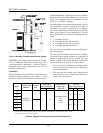
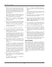
Ignition Module
When additional heat is needed, the combustion air
blower starts to purge air from the combustion chamber
for 15 seconds. On proof-of-air flow, the air-proving
switch closes and the igniter is energized. To ensure
safe operation, the gas valve cannot open until the ig-
niter is verified. The main burner is automatically lit
when the device is powered and pre-purged. The heater
performs its own safety check and opens the main
valve only after the igniter is proven to be capable of
ignition.