


SECTION D: Start up
43
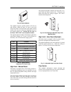
5. Check blower motor amp draw and the manometer
attached to fan pressure switch with the blower
running at 100% speed. The reading should be as
noted in Tables P and Q for both natural gas and
propane gas. If not, adjust the air shutter on the
blower to attain the correct values.
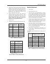
6. Measure the blower amp draw and compare the
measured values to the values in Table P. If the
measured value is different than the values in the
table (with the noted tolerance), contact the factory.
NOTE: Connect the amp probe to the 14 Ga.
black power wire going into the blower.
7. Turn power off.
8. Disconnect the manometer and reconnect the cap.
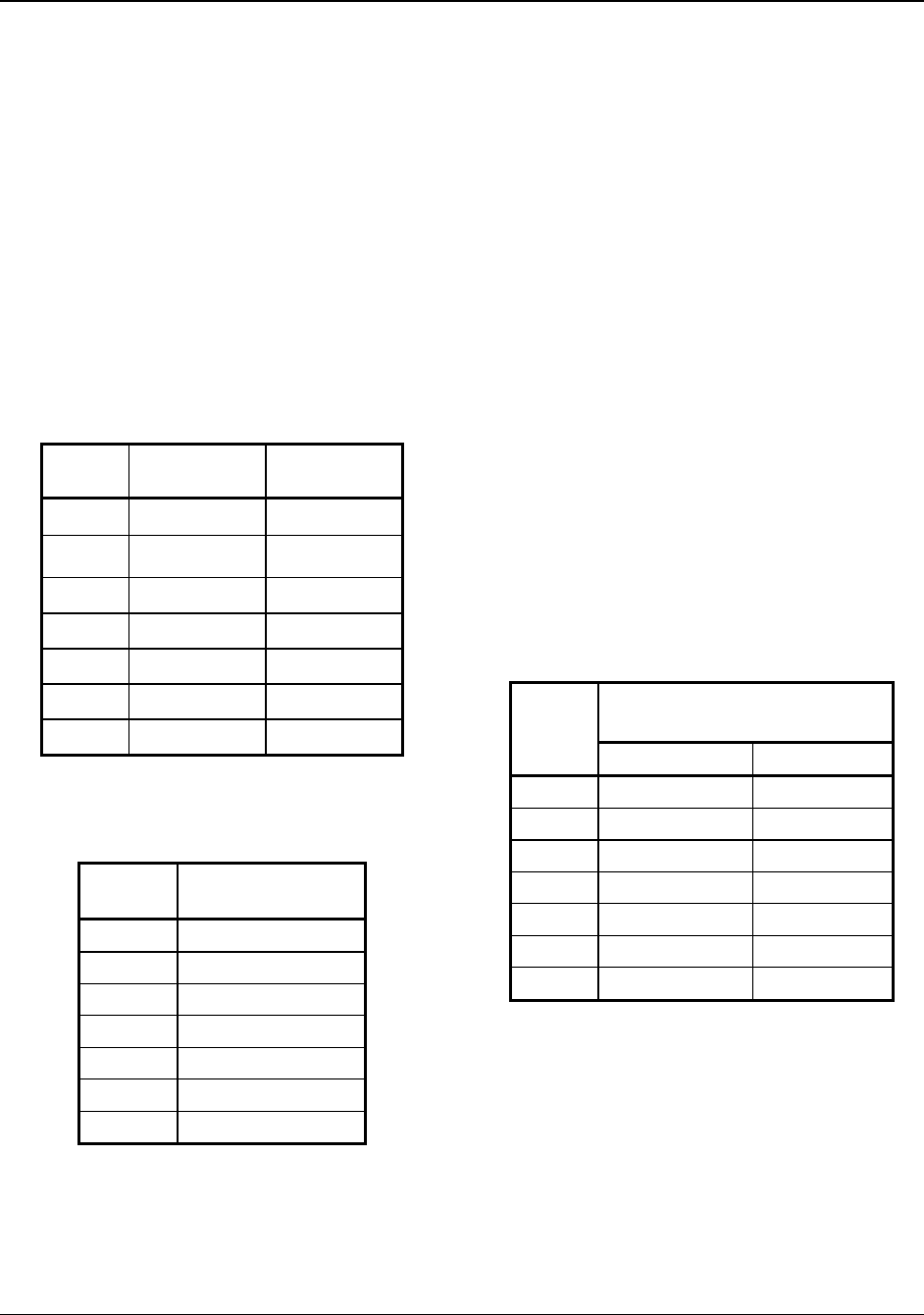
Model Amp Draw
Setting
Tolerance
503
1.9
+0.0/-0.2
753
2.9
+0.0/-0.2
1003
4.8
+0.0/-0.2
1253
6.3
+0.0/-0.2
1503
8.1
+0.0/-0.2
1753
13.5
+0.0/-0.5
2003
14.8
+0.0/-0.5
Table P: MVB Blower Amp Draw
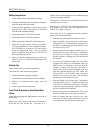
Model
Air Pressure Setting*
(in. WC)
503 -2.3
753 -2.9
1003 -3.0
1253 -3.5
1503 -4.0
1753 -4.6
2003 -4.1
* Settings +/- 0.2” WC
Table Q: MVB Air Pressure Requirements
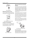
Manifold Adjustment
1. Turn off unit.
2. Open manual firing valves.
3. Turn on the unit, wait approximately 15 seconds,
and the igniter should glow (observable through
the observation port located at the front, bottom of
the heater). Look into sight glass located at the
bottom of the front panel to check igniter operation.
Gas valve should open in 45-60 seconds.
4. If burner does not light on first trial. It will go into
lockout with the standard ignition module. If it is
equipped with the optional 3-try ignition module,
it will try for ignition up to three times.
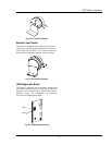
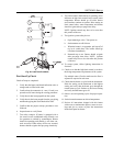
5. Main burner ignition: Check manifold gas pressure
at gas valve outlet pressure tap (connection “C” in
Fig. 39). This should read per the values in Table
R for natural gas and propane gas.
6. If the pressure reading differs by more than ± 0.2
in. WC, STOP – Call the factory for directions on
what to do next!
CAUTION: Special manifold and air settings may be
required.
Manifold Gas Pressure Setting*
High Fire Values (in. WC)
Model
Natural Gas LP Gas
503 -0.1 -0.1
753 -0.1 -0.1
1003 -0.2 -0.2
1253 -0.1 -0.1
1503 -0.4 -0.3
1753 0.4 0.4
2003 0.6 0.6
* Settings +/- 0.2” WC
Table R: MVB Manifold Gas Pressure Settings