


SECTION C: Installation
36
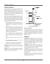
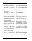
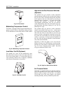
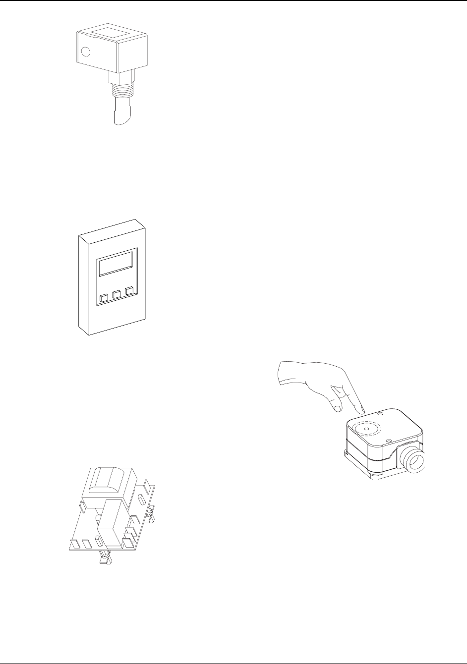
Fig. 32: Flow Switch
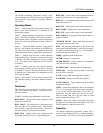
Modulating Temperature Control
The heater is equipped with a Raypak modulating tem-
perature control. Refer to information starting on page
28 for information on the setting and use of this control.
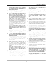
Fig. 33: Modulating Temperature Control
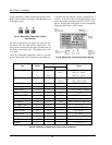
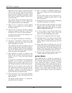
Low Water Cut-Off (Optional)
The optional low water cut-off automatically shuts
down the burner whenever water level drops below the
level of the sensing probe. A 5-second time delay pre-
vents premature lockout due to temporary conditions
such as power fluctuations or air pockets.
Fig. 34: Low Water Cut-Off
High and Low Gas Pressure Switches
(Optional)
The optional low gas pressure switch connection
mounts upstream of the gas valve (on the inlet flange to
the gas valve) and is accessible through the removable
access panels on the rear of the heater to reset the gas
pressure switch, as necessary. It is used to ensure that
sufficient gas pressure is present for proper
valve/regulator performance. The low gas pressure
switch automatically shuts down the heater if gas sup-
ply drops below the factory setting of 3.0 in. WC for
natural gas or LP gas.
The optional high gas pressure switch connection
mounts down-stream of the gas valve. Special ports
are located on the backside of the gas valve and acces-
sible from the front of the heater (to reset the gas
pressure switch) or through the removable access pan-
els on the rear of the heater (to reset the gas pressure
switch), as necessary. If the gas pressure regulator in
the valve fails, the high gas pressure switch automati-
cally shuts down the burner.
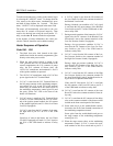
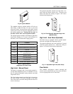
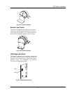
Operation of either the High or Low Gas Pressure
Switch will turn on an LED inside the switch housing.
Push the top of the plastic switch housing as shown in
Fig. 35 to reset a tripped pressure switch. The LED
will go out when the switch is reset.
Fig. 35: High/Low Gas Pressure Switch
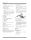
Air Pressure Switch
The heater is equipped with an air pressure switch to
prove the operation of the blower before allowing the
ignition control to begin a Call for Heat. It is located
on the right side of the lower flange of the blower
mounting assembly, directly behind the junction box.