


SECTION C: Installation
19
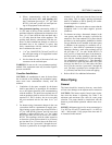
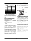
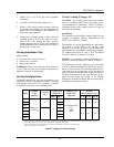
Manifold Gas Pressure
(High Fire Values)
Model
No.
Natural Gas Propane Gas
503 -0.1
-0.1
753 -0.1
-0.1
1003 -0.2
-0.2
1253 -0.1
-0.1
1503 -0.4
-0.3
1753 0.4
0.4
2003 0.6
0.6
NOTE: Manifold pressures should be + 0.2” WC.
Table I: Manifold Gas Pressure Settings
During normal operation, carbon dioxide should be 8.0
to 9.0% at full fire for natural gas and between 9.0 and
10.0% for propane gas. Carbon monoxide should be
‹100ppm.
Electrical Power Connections
Installations must follow these codes:
• National Electrical Code and any other national,
state, provincial or local codes or regulations hav-
ing jurisdiction.
• Safety wiring must be NEC Class 1.
• Heater must be electrically grounded as required by
the NEC.
• In Canada, CSA C22. 1 C.E.C. Part 1.
The MVB 503-1503 heaters are wired for 120 VAC, 12
amps while the MVB 1753 & 2003 heaters are wired
for 120 VAC, 18 amps. Consult the wiring diagram
shipped with the heater. Before starting the heater,
check to ensure proper voltage to the heater and pump.
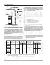
Boiler mounted pumps (up to ¾ hp) get their power
supply directly from the boiler power supply (connec-
tions in rear wiring box). Install a circuit breaker sized
sufficiently for both the heater and the pump. Pumps
larger than ¾ hp must use a separate power supply and
run the power through the optional pump contactor
which is located in the rear wiring box (see Fig. 16).
Use appropriately-sized wire as defined by NEC, CSA
and/or local codes. All primary wiring should be 125%
of minimum rating.
If any of the original wire as supplied with the heater
must be replaced, it must be replaced with 105°C wire
or its equivalent.
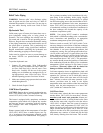
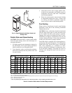
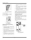
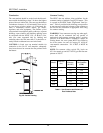
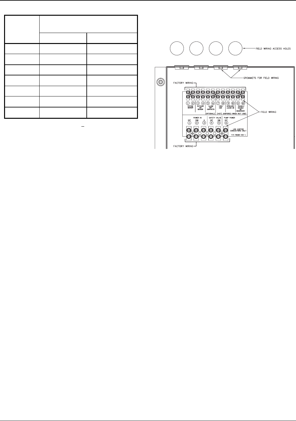
Fig. 16: Rear Wiring Box Electrical Connections
All field wiring connections to the MVB heater are
made inside the rear wiring box as shown in Fig. 16.
Pump power should be taken from terminals 2 (Com),
3 (GND) and 6 (Hot) – ¾ hp and smaller ONLY.
Power to the MVB heater should be connected to ter-
minals 1, 2, and 3 as noted in Fig. 16. Sensors,
interlocks, Enable/disable, and various options are
wired into terminals 1 – 12 as noted in Fig. 16.
Field-Connected Controllers
It is strongly recommended that all individually-
powered control modules and the heater should be sup-
plied from the same power source.
NOTICE: Field-supplied isolation relays should be
installed when field-connected controllers are mounted
more than 50 equivalent feet (18 Ga) from heater.
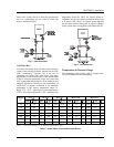
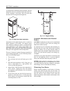
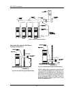
Check the Power Source
WARNING: Using a multi-meter, check the following
voltages at the circuit breaker panel prior to connecting
any equipment. Make sure proper polarity is followed
and house ground is proven. (See Fig. 17.)