


SECTION C: Installation
23
5. Within 6 ft (1.8 m) of any gas service regulator
vent outlet.
6. Less than 1 ft (305 mm) above grade level.
7. Within 3 ft (0.9 m) of a window or door which can
be opened in any building, any non-mechanical air
supply inlet to any building or the combustion air
inlet of any other appliance.
8. Underneath a verandah, porch or deck, unless the
verandah, porch or deck is fully open on a mini-
mum of two sides beneath the floor, and the
distance between the top of the vent termination
and the underside of the verandah, porch or deck is
greater than 1 ft (305 mm).
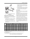
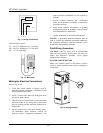
Venting Installation Tips
Support piping:
• horizontal runs - at least every 5 ft
• vertical runs - use braces
• under or near elbows
WARNING: Examine the venting system at least once
a year. Check all joints and vent pipe connections for
tightness, corrosion or deterioration.
Venting Configurations
For heaters connected to gas vents or chimneys, vent
installations shall be in accordance with Part 7, Venting
of Equipment, of the NFGC (U.S.), or B149.1 (Canada),
or applicable provisions of local building codes.
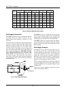
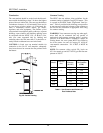
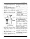
Vertical Venting (Category IV)
CAUTION: This venting system requires the installa-
tion of a condensate drain in the vent piping per the
vent manufacturer’s instructions. Failure to install a
condensate drain in the venting system will void all
warranties on this heater.
Installation
The maximum and minimum venting length for this
Category IV appliance shall be determined per the
NFGC (U.S.) or B149.1 (Canada).
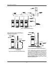
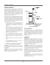
The diameter of vent flue pipe should be sized accord-
ing to Part 11 of the NFGC (U.S.) and Part 7 and
Appendix B of B149.1 (Canada). The minimum flue
pipe diameter for conventional venting using Category
IV, stainless steel AL29-4C vent is: 6 in. for Models
503-1003; and 8 in. for Models 1253-2003.
NOTICE: A vent adapter (field-supplied) may be re-
quired to connect the Category IV vent to the heater.
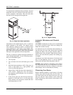
The connection from the appliance vent to the stack
must be as direct as possible and shall be the same di-
ameter as the vent outlet. The horizontal breaching of a
vent must have an upward slope of not less than 1/4
inch per linear foot from the heater to the vent terminal.
The horizontal portions of the vent shall also be sup-
ported for the design and weight of the material
employed to maintain clearances and to prevent physi-
cal damage or separation of joints.
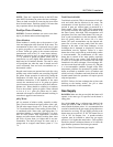
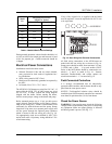
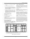
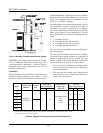
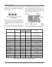
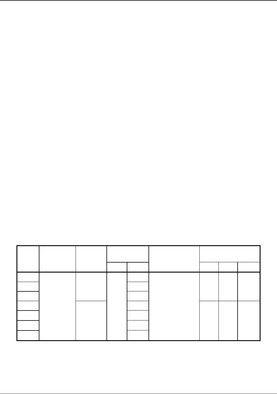
Vertical Vent
Height
1
(Ft)
Air Inlet
Max. Length** (Ft)
Model
Certified
Vent
Material
Vent Size
(in.)
Min. Max.
Combustion Air
Intake Pipe
Material
6” Ø 8” Ø 10” Ø
503 15
*
753 75
1003
6
75
45 100 N/A
1253 40
1503 75
1753 75
2003
Category IV
(AL29-4C)
8
0
75
Galvanized Steel,
PVC,
ABS,
CPVC
N/A 45 85
* Vent length may be extended up to 40 ft. using a barometric damper installed at 15 equivalent feet from the heater where the category of the
vent changes from Cat IV to Cat II. NOTE: Special vent materials are still required.
1
Vent lengths are based on a lateral length of 2 ft. Refer to the latest edition of the NFGC for further details.
** Subtract 10 ft per elbow. Max. 4 elbows.
Table K: Category IV Vertical Venting