31
size, and connections which comply with all applicable
codes.
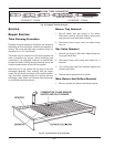
7,80#:77 @?$,10?D$B4?.3
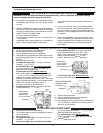
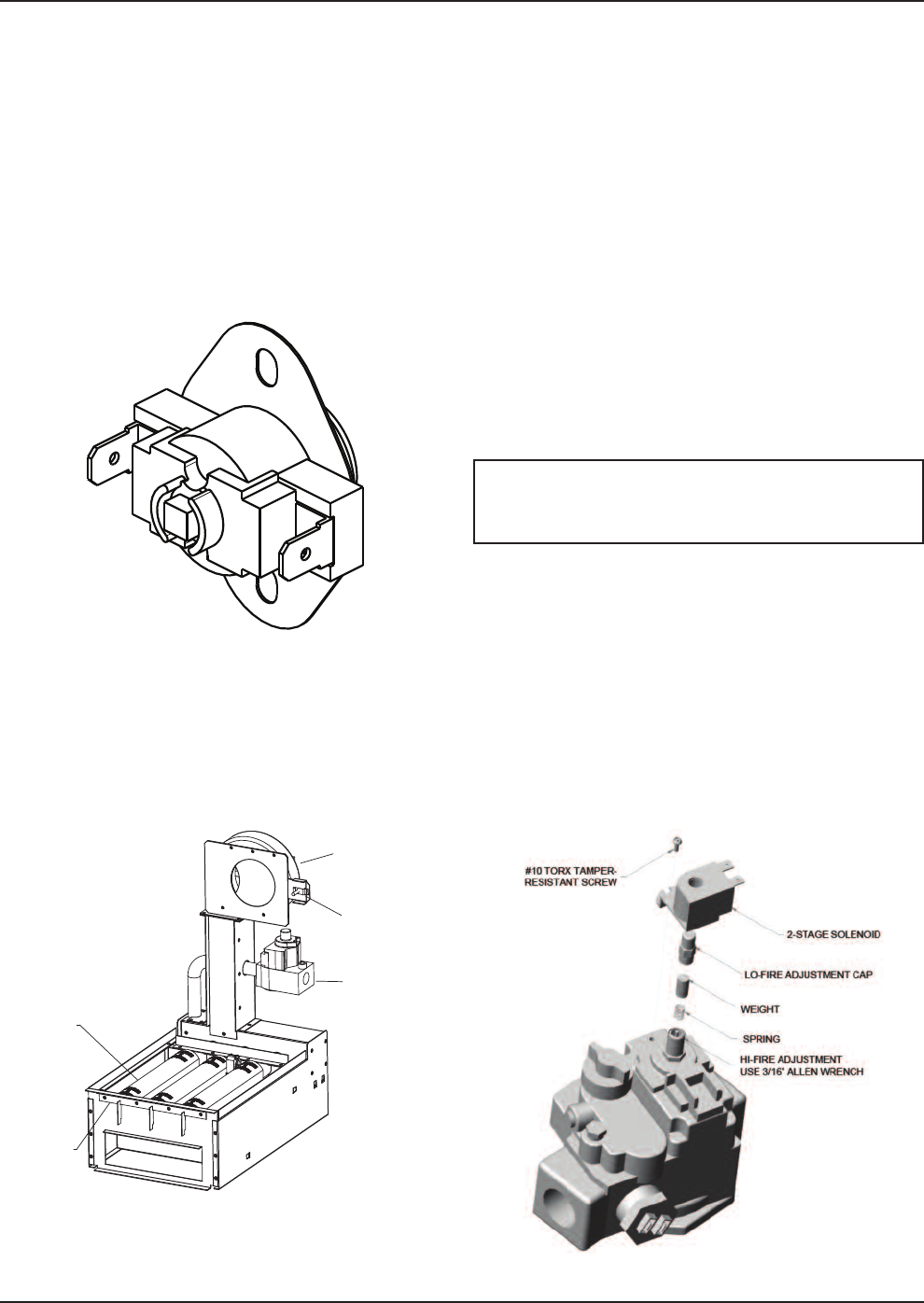
The boiler is equipped with a cut-off device to prevent
f
lame roll-out in the event the heat exchanger
becomes blocked. This is a "manual reset" type roll-
out switch, that must be reset by a service technician
after any over temperature conditions have been fixed.
Excessive restriction in the heat exchanger flue pas-
sage may cause the switch to disable the boiler.
$0=A4.0
@=90=%=,D#08:A,7
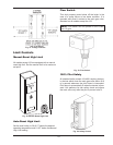
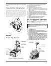
Fig. 45: Flame Roll-Out Safety Switch
1. Shut-off main electrical power switch to heater.
2. Shut-off gas upstream of heater.
3. Remove front door.
4. Disconnect gas line from gas valve.
5. Remove (2) screws that mount burner tray to the
base of the unit, and (2) screws that secure gas
valve to jacket.
6. Disconnect wires that terminate at gas valve.
7. Unscrew (4) screws that secure the control box.
8. Disconnect pilot wire from the ignition module.
9. Disconnect wire harness from the combustion
blower.
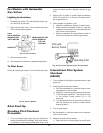
10. Carefully slide out the burner tray assembly.
11. Reverse above procedure to re-install.
,>',7A0/5@>?809?#:-0=?>3,B
9A09>D>$0=40>$?,20,>
',7A0B4?3$:709:4/',7A0
1. Turn the heater off.
2. Remove the 3/8” nut or the #10 Torx screw.
3. Lift solenoid valve up, keeping the wires connect-
ed to the solenoid valve.
4. If only low fire adjustment is needed, go to Step 9.
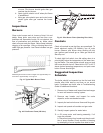
5. Using a 3/8” wrench, carefully remove the alu-
minum cap that was under the solenoid
valve-count # of turns when removing the cap.
Be careful not to drop the cylinder (weight) or the
small spring that is under the cap –see Fig. 47.
6. Remove the spring and store in a safe place.
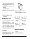
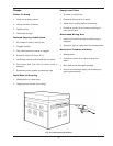
BURNER
BURNER
HOLD-
DOWN
BRACKET
GAS
VALVE
COMBUSTION
AIR BLOWER
AIR SHUTTER
ADJUSTMENT
Fig. 46: Low NOx Burner Tray Assembly
% Attach a manometer and check the manifold
pressures –both high fire and low fire– before
making any adjustments.
Fig. 47: 2-Stage Gas Valve Adjustment (Invensys)


