18
RDHRDHLEDOM
SIZE GPM
T P FT GPM T P FT CONN GPM T P FT GPM T P FT CONN
133* 22 10 14.7 10 22 3.3 1-1/4"
182/181
45 7 9.2 20 15 1.8
1-1/2"
2
60/261
45 10 9.4 20 22 1.9
1-1/2"
330/331
45 12 9.6 20 28 1.9
1-1/2"
400/401
45 15 9.8 20 33 2.0
1-1/2"
5
14
90 9 9 40 21 1.8
2"
624
90 12 9.5 40 26 1.9
2"
724
90 13 10 40 30 2.0
2"
8
24
90 15 10.5 40 34 2.1
2"
926
90 17 11 40 38 2.2
2
1/2"
200 8 9.7
9
0172.13"
962
90 18 11 40 40 2.2
2 1/2"
200 8 9.7
90 18 2.1 3"
1083
90 20 12 45 40 3.1
2 1/2"
200 9 10.3
90 20 2.3 3"
1125
90 21 12 47 40 3.3
2
1/2"
200 9 10.3
9
0202.33"
1178
90 22 12.5 49 40 3.8
2 1/2"
200 10 11
90 21 2.4 3"
1223
90 22 12.5 51 40 4.0
2 1/2"
200 10 11
90 22 2.4 3"
1287
90 24 13.2 53 40 4.5
2 1/2"
200 11 11.7
90 23 2.5 3"
1336
90 24 13.2 55 40 4.9
2 1/2"
200 11 11.7
90 24 2.5 3"
1414
90 26 14 58 40 5.8
2 1/2"
200 12 12.2
90 26 2.7 3"
1468
90 27 14 61 40 6.4
2 1/2"
200 12 12.2
90 27 2.7 3"
1571
90 29 14.5 65 40 7.5
2 1/2"
200 13 13
90 29 2.8 3"
1631
90 30 14.5 68 40 8.3
2 1/2"
200 13 13
90 30 2.8 3"
1758
90 32 15.4 73 40 10.0
2 1/2"
200 14 14.7
90 32 3 3"
1826
90 34 15.4 76 40 10.8
2 1/2"
200 15 14.7
90 33 3 3"
2100
200 17 14.8 90 39 3.2
3"
400 9 18
180 19 4 4"
2500
200 21 15.8 103 40 4.4
3"
400 10 18.8
180 23 4.1 4"
3001
200 25 16.7 124 40 6.7
3"
400 12 19.5
180 27 4.3 4"
3500
200 29 17.5 145 40 9.5
3"
400 14 20.5
180 32 4.5 4"
4001
200 33 18.7 166 40 13.0
3"
400 16 21.5
180 36 4.7 4"
MAXIMUM AND MINIMUM FLOW RATES
2
-PASS HEAT EXCANGER
1
-PASS HEAT EXCHANGER
NIMXAMNIMXAM
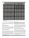
GPM Flow rates limited by maximum acceptable velocity through heat exchanger tubes. May be increased by 10% for closed heating
systems.
* 4 Pass Heat Exchanger
BOLD TYPE indicates Low NOx models.
difference between the inlet and outlet water when the
boiler is firing at full rate). For some boilers, the Delta
T is more than 20°F (22°-33°F) at the recommended
flow rates.
00/B,?0=#02@7,?:=
We recommend that a feedwater regulator be installed
and set at 12 PSIG minimum pressure. Install a check
valve or back flow device upstream of the regulator,
with a manual shut-off valve. Leave the valve open.
!4;492H0,?492:470=>
We recommend that all high points be vented and that
purge valves and a bypass valve be installed. A boiler
installed above radiation level must be provided with a
low water cut-off device. The boiler, when used in con-
junction with a refrigeration system, must be installed
so that the chilled medium is piped in parallel with the
boiler with appropriate valves to prevent the chilled
medium from entering the boiler.
#0.:8809/0/!@=20,941:7/>1:=
%D;4.,7D/=:94.$D>?08::6@;>
The boiler piping system of a hot water heating boiler
connected to heating coils located in air handling units
where they may be exposed to refrigerated air circulat-
ing, must be equipped with flow control valves or other
automatic means to prevent gravity circulation of the
boiler water during the cooling cycle.
%08;0=,?@=0!=0>>@=0,@20
The temperature & pressure gauge is standard equip-
ment on all hydronic heating and hot water supply
boilers. All temperature & pressure gauges are factory
mounted in the in/out header except for residential
boilers, Models 133 and 181-401. On these models
the temperature & pressure gauge is shipped loose for
field installation, and located in the outlet water con-
nection. All fittings required to mount gauge to piping
system are supplied by others.
Table H: Maximum and Minimum Flow Rates


