21
%# $
.:9:8,>?0=:9?=:7>
T
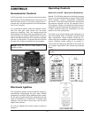
he Economaster II is an electronic device that allows
the operator to set the desired time for the pump to run
after the boiler shuts off. The time is factory-set at 7
minutes and it can be re-adjusted in the field anywhere
from 3 to 10 minutes.
In a conventional system, when the aquastat is satis-
fied, the main gas valve closes, but the pump
continues operating. With the energy-conserving
Economaster II the boiler pump is programmed to con-
tinue running for an optimum period of time in order to
absorb the residual heat from the combustion chamber
and use it in the system. The pump then shuts off until
the next call for heat is received from the aquastat.
70.?=:94.294?4:9
The intermittent ignition device conserves energy by
automatically extinguishing the pilot when desired
temperature is reached. When additional heat is need-
ed, the pilot re-ignites electrically, eliminating the fuel
costs of maintaining a constant pilot. To ensure safe
operation, the gas valve cannot open until the pilot
relights and is proven.
All units are shipped with lockout ignition module as
standard.
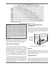
% Pump will come on when power is first
applied to boiler.
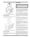
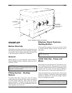
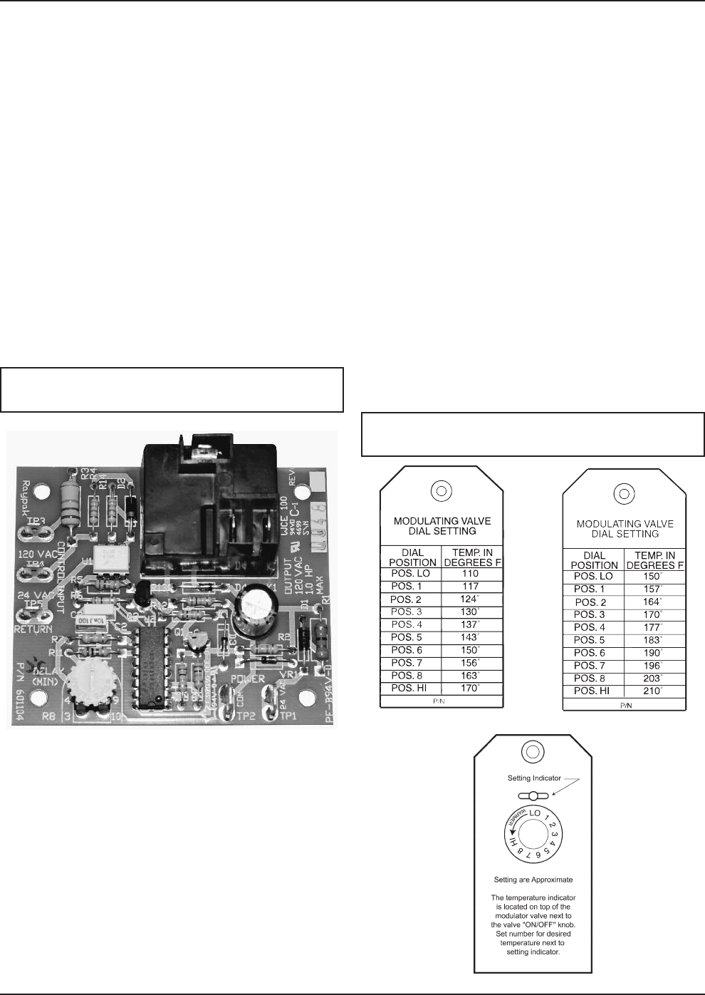
Fig. 26: Economaster PCB
;0=,?492:9?=:7>
:/0>,9/0.3,94.,7:/@7,?4:9
M
odels 133-1826 with mechanical modulating controls
have one or more Robertshaw (Invensys) Unitrol 7000
Series hydraulic snap-on thermostatic combination
gas valves. These dual-seat combination valves have
the pressure regulator and 24 volt operator built-in.
The hydraulic actuator will throttle the boiler input to
adjust the firing rate and meet the required load. This,
in effect, prevents costly fuel consumption, as com-
pared to an on-off cycling boiler.
The valve has a remote capillary bulb immersed in a
well, at the header outlet, to maintain a constant outlet
water temperature. When multiple valves are fur-
nished, they can be staged to give greater flexibility of
control. Standard factory setting is at position 5.
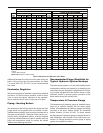
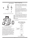
Consult the dial setting tag attached to the control for
your desired temperature. See sample tag drawings
below.
INVENSYS
INVENSYS
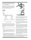
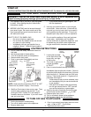
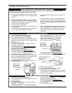
Fig. 27: Sample Tags
Low Temp. Range High Temp. Range
% No external control of the valve position is
possible.


