28
:=:/07>B4?3@?:8,?4.
,>',7A0>
423?4929>?=@.?4:9>
1. Close all gas valves. Turn off electrical power sup-
ply. Wait five (5) minutes.
2. Open manual pilot valve. Turn on electrical power.
Pilot is automatically lighted.
3. Open main gas valve.
4. Set temperature controls to desired temperature.
%:$3@?:B9
Close all manual gas valves. Turn off electrical power.
1?0=$?,=?&;
$?,9/492!47:?30.6:@?
!=:.0/@=0
1. Turn on pilot gas supply, light pilot, and check pilot
tubing connections for leakage. With main burner
in operation, paint tubing connections with a rich
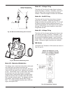
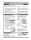
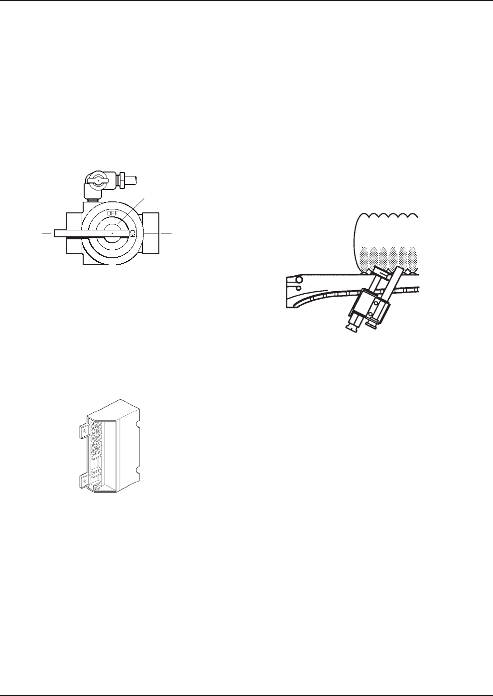
PILOT
VALVE CONTROL
SHOWN IN THE MAIN GAS SHUT-OFF
"ON" POSITION VALVE SHOWN IN
THE "ON"
POSITION
GAS
INLET
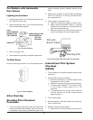
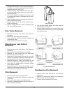
Fig. 38: Shut Off Valve
Fig. 39: Ignition Module
soap and water solution. Bubbles indicate a gas
leak.
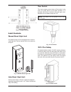
2. Adjust pilot to obtain a normal flame enveloping
3/8 to 1/2 inch [9.5 to 12.5 mm] of the thermocou-
ple or generator tip.
3. Place system in operation, and:
a. Check for satisfactory ignition of main burner.
b. Make certain the pilotstat "holds in", and that
shutdown occurs within 2-1/2 minutes after the
pilot flame is extinguished.
c. Observe operation for at least three cycles to
be sure the system is functioning normally.
9?0=84??09?!47:?$D>?08
30.6:@?
$
1. Turn on power to the ignition systems and turn gas
supply off.
2. Check ignition module as follows:
a. Set the thermostat or controller above room
temperature to call for heat.
b. Watch for continuous spark at the pilot burner.
c. Time the spark operation. Time must be with-
in the lockout timing period (15 or 90
seconds).
d. Turn thermostat down to end call for heat and
wait 60 seconds on lockout models before
beginning step 3.
3. Turn on gas supply.
4. Set thermostat or controller above room tempera-
ture to call for heat.
5. Systems should start as follows:
a. Spark will turn on and pilot gas valve will open
Pilot with
Burner Flame
Standing Pilot
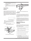
Fig. 40: Pilot Flame Should Engulf Thermocouple


