


39
F. TEST HIGH LIMIT CONTROL AND ADJUST
While burner is operating, move indicator on high limit control below actual boiler water
temperature. Burner should go off while circulator continues to operate. Raise limit setting
above boiler water temperature and burner should reignite after pre purge and igniter warm-
up period. Set the high limit control to the design temperature requirements of the system.
Maximum high limit setting is 200
°
F. Minimum high limit setting is 100°F.
G. TEST OTHER SAFETY CONTROLS
If the boiler is equipped with a low water cut off, a manual reset high limit, or additional safety
controls, test for operation as outlined by the control manufacturer. Burner should be operat-
ing and should go off when controls are tested. When safety controls are restored, burner
should reignite.
H. SET THERMOSTAT HEAT ANTICIPATOR (IF USED) AND VERIFY THERMOSTAT OPERATION
For a single thermostat connected to the yellow thermostat lead wires in the furnished field
wiring junction box, the heat anticipator should be set at 0.7 amps. For other wiring configura-
tions, refer to the instructions provided by the thermostat manufacturer regarding adjustment
of heat anticipator. Cycle boiler with thermostat. Raise the thermostat to the highest setting
and verify boiler goes through normal start up cycle. Lower thermostat to lowest setting and
verify boiler goes off.
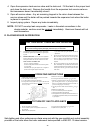
I. MEASURE THE NATURAL GAS INPUT RATE
Correct input rate is essential for proper and efficient operation of the burner and boiler.
1. Determine elevation at installation site.
2. See page 4 and 5 of this manual to determine the correct input rate for the local elevation.
3. Obtain the yearly average heating value of the local gas supply from the gas utility. At sea
level elevation, it should be approximately 1000 Btus per standard cubic foot.
4. Operate boiler for 5 minutes.
5. Turn off all other gas appliances, extinguishing standing pilots where applicable.
6. At gas meter, measure time in seconds required to use one cubic foot of gas.
7. Calculate input rate according to the following formula:
3600xheating value from step 3
B tuh input rate = time from step 6
8. Measured input rate should be within +/-2% of the input rating from step 2. If within 2%, go
to step 9. If not, adjustment is required, proceed as follows:
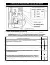
a. Turn boiler off
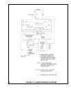
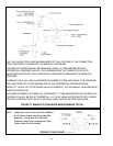
b. Set up U-tube manometer or differential pressure gauge for measuring manifold pres
sure, see FIG. 17.
c. Manometer or gauge must be able to read at least 0.0 to 3.0 inches water column of
pressure, and resolve to at least 0.1 inches water column.
d. Turn boiler on.
e. Manifold pressure has been nominally set at 2.5 inches w.c. Manifold pressure and input
rate must always be measured with pressure regulator cover screw installed. Cover screw
must be removed for adjustment. Manifold pressure reading will change (increase) when
cover screw is removed.