


20
E. FILLING CONDENSATE TRAP WITH WATER ON THE INITIAL START UP THE CONDEN
SATE TRAP MUST BE MANUALLY FILLED WITH WATER
The following are the steps required to initially fill the condensate trap for start up, these steps
are only required at the initial start up or if maintenance requires draining of the condensate trap:
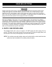
1. Disconnect the vent condensate drain line from the bottom of the vent tee on the boiler.
2. Pour about 1 cup of cold tap water into the vent drain line with a proper funnel.
3. Excess water should go through the overflow and out through the condensate drain line.
Verify proper operation of the drain line (or external condensate pump if used).
4. Reinstall the vent drain line.
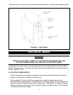
F. CHILLED WATER PIPING
The boiler, when used in connection with a refrigeration system, must be installed so the
chiller medium is piped in parallel with the boiler with appropriate valves to prevent the chilled
medium from entering the boiler.
The boiler piping system of a hot water boiler connected to heating coils is located in air
handling units where they may be exposed to refrigerated air circulation must be equipped
with flow control valves or other automatic means to prevent gravity circulation of the boiler
water during cooling cycle.
A. CONNECTIONS AND TERMINATION
For boilers connected to gas vents or chimneys, vent installations shall be in accordance with
part 7, Venting of Equipment, of the National Fuel Gas Code, ANSI 2223.1-latest revision,
CAN/CGA-B 149.1 and B 149.2, and applicable provisions of the local building codes.
Provisions for combustion and ventilation air must be in accordance with section 5.3, Air For
Combustion and Ventilation, of the National Fuel Gas Code,ANSI 2223.1-latest revision,
CAN/CGA-B 149.1 and B 149.2, or applicable provisions of the local building code.
These boilers require a dedicated direct vent system. All air for combustion is taken directly
from outdoors through the combustion air intake pipe. All flue products are discharged to the
outdoors through the vent pipe.
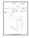
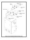
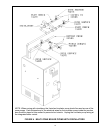
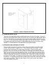
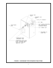
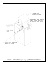
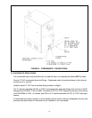
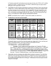
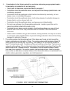
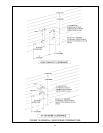
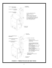
1. See Fig.9 & 10 for combustion air and vent pipe roof and sidewall termination. (Roof termi
nation is preferred) Combustion air and vent pipes must terminate together in same atmo
spheric pressure zone as shown. Construction through which vent and air intake pipes
may be installed is a maximum 24 inches, minimum
1
/4" thickness.
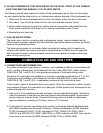
2. Combustion air and vent pipe fittings must conform to American National Standards Insti
tute (ANSI) standards and American Society for Testing and Materials (ASTM) standards
D1784 (schedule-40 CPVC), D1785 (schedule-40 PVC), D2665 (PVC-DWV), D2241
(SDR-21 and SDR-26 PVC), D2661 (ABS-DWV), or F628 (schedule-40 ABS). Pipe cement
and primer must conform to ASTM standards D2564 (PVC) or D2235 (ABS).
COMBUSTION AIR AND VENT PIPE