


33
higher aquastat setting or over firing. The temperature safety switch automatically resets
when the vent temperature decreases. (15 °F switch differential).
F. CASTING TEMPERATURE SAFETY SWITCH
In the event of lack of or loss of water in the boiler, the Casting Temperature Safety Switch
(300 °F setpoint) installed on the top of the aluminum boiler section shuts off the boiler by
shutting off power to the Integrated Boiler Control (IBC) and causes the Power Indicator Light
to go out. This fault requires manual reset of the casting temperature safety switch to restart
the boiler. Verify that the boiler is properly filled with water before resetting this switch.
WARNING-Never run cold water into a hot empty boiler.
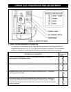
G. DIFFERENTIAL PRESSURE AIR PROVING SWITCH
The diaphragm type differential pressure switch is connected by vinyl tubing to the pressure
signal hose adapters. The pressure switch monitors air flow by sensing the diffential
pressure measured in inches of water( w.c.). The factory settings on these switches are
1.00 w.c. for Model-100, 1.35 w.c. for Model-75 and 1.55 w.c. for Model-50. The contacts
are normally open, and close when the draft inducer is running and causing the diffential
pressure at the switch to exceed the setting. The closed switch proves there is adequate air
flow for combustion. The pressure switch shuts off the main burner if the differential pressure
is inadequate due to a blocked vent pipe or a blocked air intake or blocked boiler sections or
blocked draft inducer. After five (5) minutes of lack of the adequate differential pressure, the
IBC will lockout. The PURGE indicator light will blink, indicating a failure to prove adequate
combustion air flow or flue gas flow. The IBC is manually reset from lockout as described in
the Sequence of Operation section of this chapter.
H. DRAFT INDUCER
The draft inducer (blower) provides a means for pulling combustion air into and through the
mixer, the burner, the flue ways of the cast aluminum boiler sections and the flue adapter
before being discharged through the vent piping to the outdoors. See applicable sections for
proper sizing and installation of combustion air and vent piping in this manual.
I. CIRCULATOR PUMP
Every forced hot water system requires at least one circulating pump. The circulating pump
imparts the necessary energy to move the water through the closed loop supply and return
piping systems, terminal heating equipment (i.e. finned tube radiators, etc.) and back
through the boiler for reheating. To provide the required hot water flow rates, the circulator
pump must be properly sized to overcome frictional losses (usually measured in feet of
water, also referred to as pump head loss) of the supply and return piping systems and
boiler. The circulator pump is furnished in a carton within the boiler cabinet for a single zone
or zone valve controlled heating system and should be correctly located on the downstream
(i.e., pumping away) side of the expansion tank. For a pump controlled system (where there
is a circulator for each zone) the circulator provided with the boiler can work for one zone.
For more details on piping and circulators, see Near Boiler Piping section of this manual.
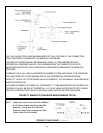
J. DRAIN VALVE
The manual drain valve provides a means of draining the water in the heating system, including
the boiler and hot water supply and return piping systems installed above the drain valve. This
drain valve is installed in the 3/4" tapping at the bottom of the front boiler section. Any piping
installedbelow the elevation of this drain valve will require additional drain valves to be installed
at low points in the piping systems in order to drain the entire system.