


28
to either of the unused brass screws on the service switch. Connect the white (neutral) lead from
the power supply to the white screw on the service switch. Connect the green (ground) lead
from the power supply to the ground (green) screw on the service switch. The receptacle on the
service switch is always powered regardless of whether the switch is on or off, and could be
used as a power supply for an external condensate pump if one is used.
The boiler, when installed, must be electrically grounded in accordance with the requirements of
the authority having jurisdiction or, in the absence of such requirements, with the National Elec-
trical Code, ANSI/NFPA-70, latest revision. In Canada, electrical wiring shall comply with the
Canadian Electrical Codes, CSA-C22.1 and .2.
Run a 14 gauge or heavier copper wire from the boiler to a grounded connection in the service
panel or a properly driven and electrically grounded ground rod.
B. INSTALL YOUR THERMOSTAT
The thermostat location has an important effect on the operation of your boiler system. BE
SURE TO FOLLOW THE INSTRUCTIONS INCLUDED WITH YOUR THERMOSTAT.
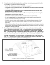
Locate the thermostat about five feet above the floor on an inside wall. It may be mounted di-
rectly on the wall or on a vertical mounted outlet box. It should be sensing average room tem-
perature. Avoid the Following:
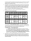
DEAD SPOTS: COLD SPOTS: HOT SPOTS:
Behind doors Concealed pipes or ducts Concealed pipes Lamps
Comers and alcoves Stairwells - drafts Fireplace Direct sunlight
Unheated rooms on TV sets Kitchens
other side of wall Radios
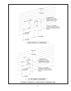
Set heat anticipator at 0.7 amps. Connect 24 volt thermostat leads to the two(2) yellow wires
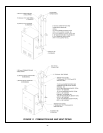
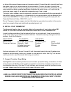
located in service switch junction box, located on outer jacket of boiler. See Fig.13 for service
switch junction box and thermostat field wiring connections.
C. Connect Circulator Pump Wiring
See Fig.13 for service switch junction box and circulator pump field wiring connections. A 5 feet
wiring harness with flexible metal conduit is supplied to connect the circulator pump to the ser-
vice switch junction box. If the two 120 volt circulator wire terminals inside the junction box are
not used, please leave the two wire nuts to prevent the short circuit.
CAUTION
LABEL ALL WIRES PRIOR TO DISCONNECTION WHEN SERVICING CONTROLS. WIRING
ERRORS CAN CAUSE IMPROPER AND DANGEROUS OPERATION. VERIFY PROPER
OPERATION AFTER SERVICING.