


This section provides a brief description of the key controls and accessories found in this boiler.
See the Troubleshooting section of the Service Hints chapter of this installation manual for detailed
sequences of operation and troubleshooting procedures. See the Repair Parts chapter of this manual for
locations of all control components and accessories described.
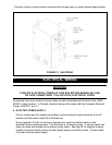
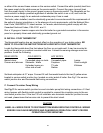
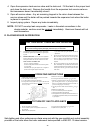
A. INTEGRATED BOILER CONTROL (IBC)
The Integrated Boiler Control (IBC) is a microprocessor based controller for a high efficiency gas
boiler that monitors all safety controls and which controls the operation of the combustion air blower,
circulator pump, burner, and a combination hot surface igniter/flame sensor. This controller is not
intended for use with a vent damper. This controller is mounted on the control panel inside of the
boiler and contains four (5) diagnostic indicator lights.
B. GAS CONTROL VALVE
The electrically controlled 24 Volt Honeywell Model VR8205 Combination Gas Control Valve is
designed to meet the requirements for use with hot surface ignition systems found in this boiler.
The valve is piped to the gas/air mixer.
C. HOT SURFACE IGNITER
The 120 volt Hot Surface Igniter heats up to 1800 °F to initiate combustion of the gas in the burner.
The igniter is mounted next to the burner through the gas/air mixer. The igniter also serves as a
means for proving the main burner flame by flame rectification. In the event of a lack of flame signal
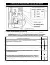
on three (3) consecutive trials for ignition, the IBC will lockout. The VALVE and FLAME diagnostic
indicator lamps (lamp D and E on the IBC, See Fig. 16) will blink indicating the failure mode as a
lack of flame signal. The IBC is manually reset from lockout by either removing and reestablishing the
thermostats call for heat, or by turning the service switch off, then back on.
D. HIGH LIMIT AQUASTAT CONTROL
The High Limit Aquastat Control determines the maximum boiler water temperature and also
provides a means for protecting the boiler and heating system from unsafe operating conditions
which could damage the boiler. The aquastat is mounted in the
½" NPT control well and ¾x½
bushing on the top of the front boiler section at the hot water outlet. The aquastat is tied in with the
IBC and is factory set at 180 °F water temperature. The high limit setpoint is field adjustable and may
be set anywhere between 100 °F and 200 °F. The field setpoint adjustment for each installation
depends on heating system requirements. The aquastat automatically resets when the boiler water
temperature decreases (5-30 °F adjustable differential). The differential can be adjusted with the
(white) Differential Adjustment Wheel on the aquastat and gives the flexibility for boiler operation. The
larger the differential, the longer the run cycle of the boiler.
NOTE: The maximum setpoint of the Aquastat must not exceed 200 °F.
E. DRAFT INDUCER TEMPERATURE SAFETY SWITCH
The Draft Inducer Temperature Safety Switch is a disc thermostat (180 °F setpoint) located on the
induced draft fan outlet port. The switch protects the inducer and vent pipe from a potential high
temperature condition for the discharging flue gases. This condition would typically be a result of
higher aquastat setting or over firing. The temperature safety switch automatically resets when the
32
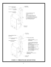
CONTROLS AND ACCESSORIES