


25
B. INSTALLATION
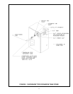
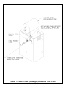
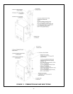
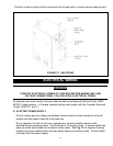
1. Attach combustion air intake piping to supplied Fernco 2" coupling on mixer. Attach
vent piping to furnished 2" CPVC vent tee on draft inducer outlet.
NOTE: All pipe joints are to be water tight.
2. Working from the boiler to the outside, cut pipe to required length(s).
3. Deburr inside and outside of pipe.
4. Chamfer outside edge of pipe for better distribution of primer and cement.
5. Clean and dry all surfaces to be joined.
6. Check dry fit of pipe and mark insertion depth on pipe.
NOTE: It is recommended that all pipes be cut, prepared, and pre-assembled before
permanently cementing any joint.
7. After pipes have been cut and pre-assembled, apply cement primer to pipe fitting
socket and end of pipe to insertion mark. Quickly apply approved cement to end of pipe
and fitting socket (over primer). Apply cement in light, uniform coat on the inside of
socket to prevent buildup of excess cement. Apply second coat.
8. While cement is still wet, insert pipe into socket with a/a turn twist. Be sure pipe is fully
inserted into fitting socket.
9. Wipe excess cement from joint. A continuous bead of cement will be visible around
perimeter of a properly made joint.
10. Handle pipe joint carefully until cement sets.
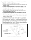
11. Support combustion air and vent piping a minimum of every 5 feet using pre-formed
metal hanging straps. Do not rigidly support pipes. Allow movement due to expansion
and contraction.
12. Slope combustion air and vent pipes toward boiler a minimum of
1
/4" per linear foot with
no sags between hangers.
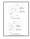
13. Use appropriate methods to seal openings where vent and combustion air pipes pass
through roof or side wall.
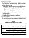
A. CHECK GAS SUPPLY
The gas pipe to your boiler must be the correct size for the length of run and for the total
BTU per hour input of all gas utilization equipment connected to it. See Table 3 for the
proper size. Be sure your gas line complies with local codes and gas company
requirements.
The boiler and its individual shutoff valve must be disconnected from the gas supply piping
system during any pressure testing of that system at test pressures in excess of /z psig (3.5kpa).
The boiler must be isolated from the gas supply piping system by closing its individual
manual shutoff valve during any pressure testing of the gas supply piping system at test
pressures equal to or less than /z psig (3.50ka).
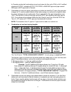
GAS SUPPLY PIPING
1$785$/*$6 3523$1(*$6
0$;,08 0*$66833/<35(6685( ´ZF ´ZF
0,1,080*$668 3 3/<35(6685( ´ZF ´ZF