


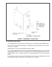
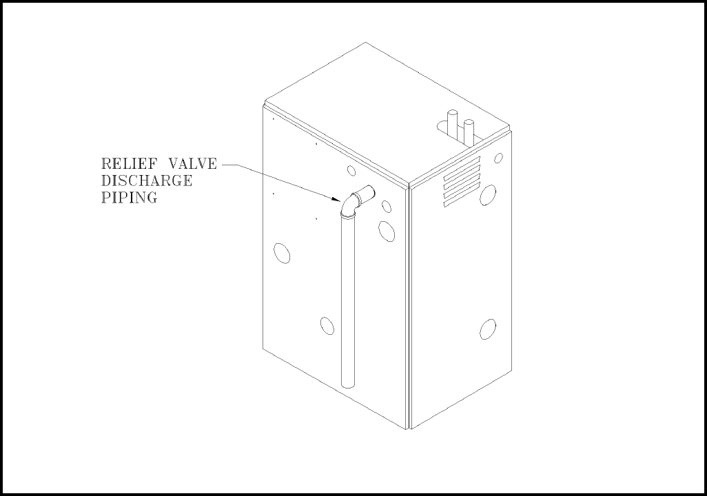
B. PRESSURE RELIEF VALVE
The boiler is furnished with a factory installed relief valve in the top of the boiler. Provide ¾
piping from the supplied relief valve to a local floor drain, but leave an air gap between piping
and drain. No shutoff of any description shall be placed between safety relief valve and the
boiler, or on the discharge pipes between such safety valve and the atmosphere. Installation
of the safety relief valve shall conform to ANSI/ASME Boiler and Pressure Vessel Code,
Section IV. The manufacturer is not responsible for any water damage.
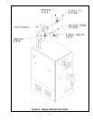
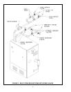
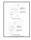
C. EXPANSION TANK AND MAKE-UP WATER
Determine required system fill pressure, system design temperature, and system water
content. Boiler contains 2.6 gallons (U.S.). Size expansion tank accordingly. Consult
expansion tank manufacturer for proper sizing information. Connect properly sized
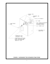
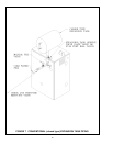
expansion tank (not furnished) as shown in Fig. 6 for diaphragm type expansion tank and
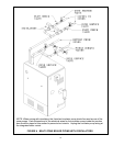
Fig. 7 for conventional closed type expansion tanks. For diaphragm type expansion tanks,
adjust the tank air pressure to match the system fill pressure. Install air vent (furnished) as
shown for diaphragm type expansion tank system only. Install make-up water connections
as shown per local codes. If a pressure reducing valve is used, adjust to match the system
fill pressure. In connecting the cold make-up water supply to the boiler, make sure that clean
water supply is available. When the water supply is from a well or pump, sand strainer
should be installed at the pump.
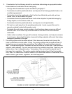
16
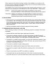
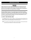
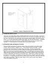
FIGURE 5 SINGLE ZONE BOILER PIPING