


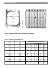
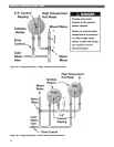
3. Mount the High Limit Control bulb well in the left
side 3/4" tapping of the coil cover plate if a tankless
heater is not mounted in the upper right opening
(Position 2). If a coil is installed there, mount the well
in the 3/4" tapping to the left of the opening. See
Figure 8.2.
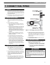
E. PIPE TANKLESS HEATERS IF USED
1. Connect piping to any installed tankless heaters. See
Figure 8.3 for suggested piping for single coils and
Figure 8.4 for suggested piping for dual coils.
F. CONNECT SUPPLY WIRING
1. Install all wiring in accordance with local codes, the
National Electrical Code and other controlling
agencies or governing bodies.
2. Use #14 gauge or heavier wire for supply wiring.
Protect the circuit with a fused disconnect switch (by
others).
3. Follow the instructions in the Burner Manual and the
Wiring Diagrams supplied with the burner and the
boiler.
G. INSTALL CONTROL WIRING
1. Wire the boiler according to the wiring diagrams
supplied with the burner and the boiler (in the Boiler
Envelope).
2. Low Energy Safety Control wiring, if used, must
follow the contour of the boiler. Some local codes
may require that all wiring, even low voltage, be
routed in conduit.
3. Install line voltage wiring in conduit.
4. Do not install single pole switches, including safety
controls, in a grounded line.
34
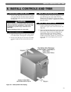
INSTALL CONTROLS AND TRIM
Make sure that the gas ignition system components,
electrical controls, junction boxes and electrical
panels are protected from water (dripping, spraying,
rain, etc.) during boiler operation and service
(circulator or pump servicing, control replacements
or other).
CAUTION
The boiler/burner must be electrically grounded in
accordance with the requirements of the authority
having jurisdiction, or in the absence of such
requirements, with the current edition of the National
Electrical Code, ANSI/NFPA Number 70.
CAUTION