


A. PREPARATION
1. Make sure the boiler has been pressure tested as
outlined in “Place the Boiler Sections” in this
manual.
2. The Supply and Return piping can be installed
before installing the jacket. Use nipples long enough
to extend through the jacket.
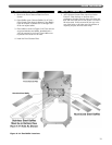
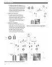
3. Install a pipe plug or nipple and cap in the 3”
tapping in the top of the tapped intermediate section
when necessary. Use only the lower side connection,
required for return piping as shown.
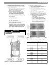
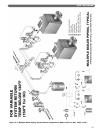
B. SUPPLY AND RETURN PIPING
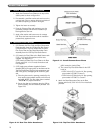
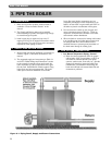
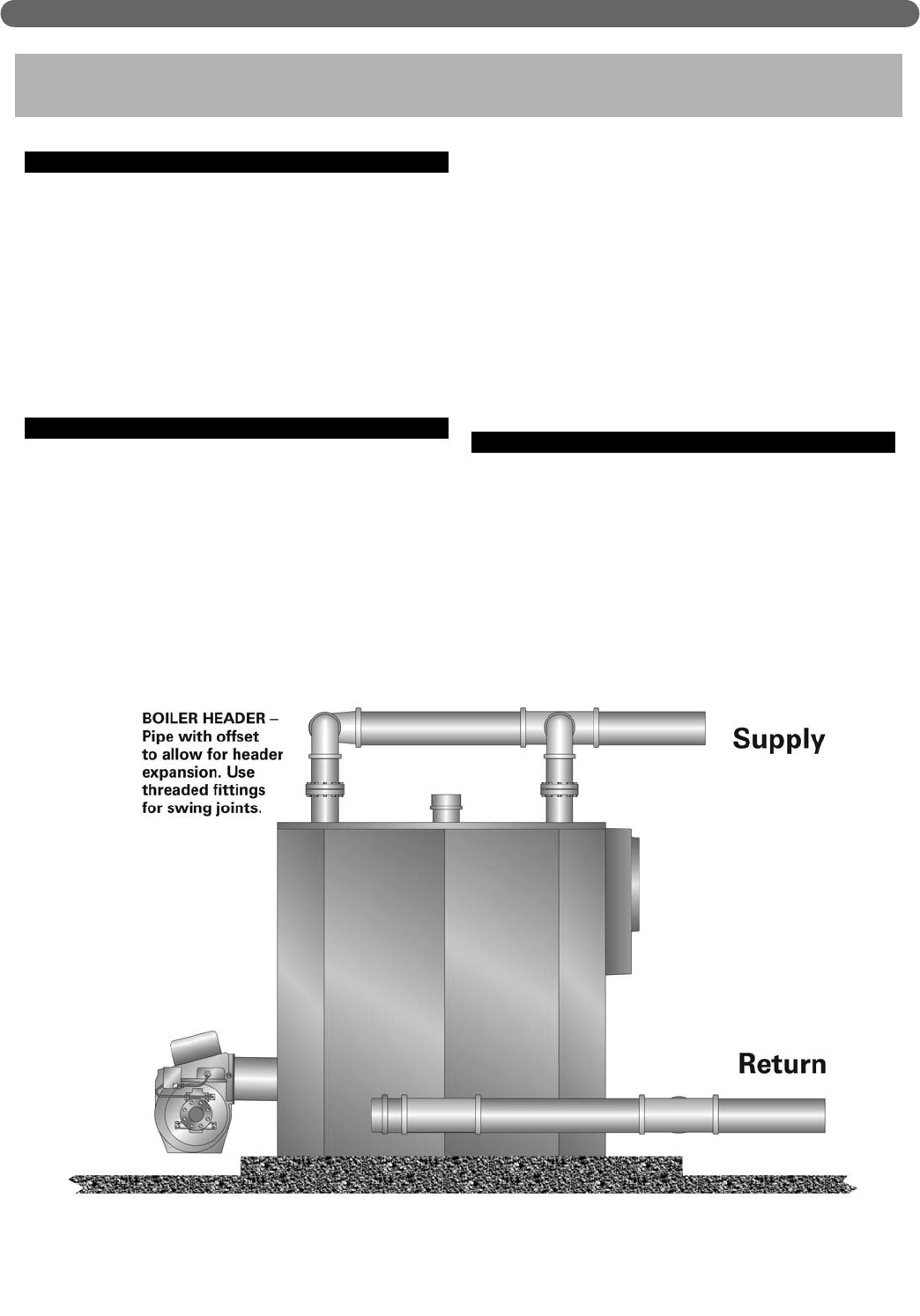
1. Always locate the Supply and Return connections as
shown in Figure 3.1 and other illustrations in this
manual.
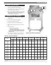
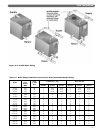
2. The suggested supply and return sizing in Table 3.1
and in the “Boiler Ratings and Dimensions” section
in this manual is based on a flow rate through the
boiler equivalent to a 20°F temperature rise (1 gpm
flow for each 10,000 Btu/Hr of boiler output). Using
higher flow rates is not recommended. This could
cause poor water flow distribution in the boiler.
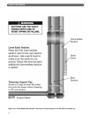
Lower flow rates (higher temperature rise) are
acceptable provided the return temperature to the
boiler is at least 130°F on gas boilers and 150°F on
oil boilers to prevent condensation of flue gases.
3. Do not reduce the number or size of supply and
return connections given in Table 3.1. These are
required to control the flow velocities in the boiler
and maintain uniform distribution.
4. When the boiler is connected to heating coils located
in air handling units, the boiler piping system must
be equipped with flow control valves or other
automatic devices to prevent gravity circulation of
the boiler water during the cooling cycle.
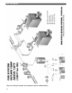
C. LOW SYSTEM TEMPERATURE
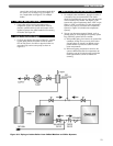
1. Low Return Temperature Piping, General
a) When the return temperature from the system
will be below 130°F on gas boilers or 150°F on
oil boilers for extended periods (heat pump
systems, outdoor reset, snow melt, etc.), provide
piping and controls to protect the boiler from
condensation. Condensation will damage the
boiler and will lead to shortened boiler life and
maintenance problems.
20
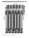
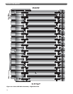
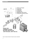
3. PIPE THE BOILER
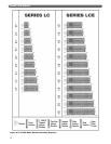
Figure 3.1: Piping Detail, Supply and Return Connections
PIPE THE BOILER