


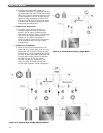
16. To properly assemble LC/LCE sections in the field,
the following steps must be followed to ensure that
no damage occurs to the tie rod lugs. A 0-100 ft-lbs
torque wrench is required.
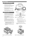
a. Use a spirit level as shown in Figure 2.4 to check
the alignment of the sections as the nuts are
drawn up. Keep the sections plumb.
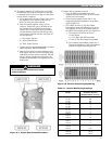
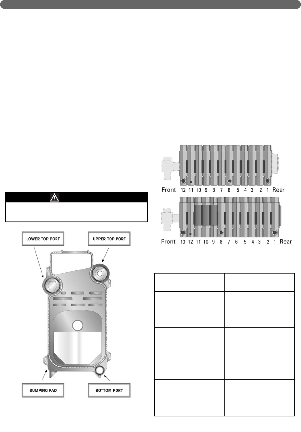
b. Draw the sections together evenly, in three
rotations. Torque each port to 20 ft-lbs for the
first rotation, then to 40 ft-lbs for the second
rotation, then to 60 ft-lbs for the third rotation.
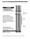
Use the following sequence until all three ports
touch metal-to-metal at 60 ft-lbs. See Figure 2.7
for port reference.
i) First: Lower Top Port
ii) Second: Bottom Port
iii) Third: Upper Top Port
c. Tighten these (3) three locations only to a torque
value of 60 ft-lbs. DO NOT EXCEED.
d. After the three ports have been tightened to 60
ft-lbs, tighten the draw rod at the bumping pads
until metal-to-metal contact is reached. This will
assure a proper gas tight seal and prevent the
products of combustion from migrating into the
boiler room.
17. Repeat with the remaining sections.
a. Save the LWCO Intermediate with two 1"
tappings (for level control) for use as the section
closest to the front section.
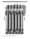
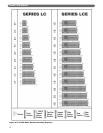
b. Place the Intermediate Section with 3" top
tapping (Tapped Intermediate) in the position
given in Figure 2.9.
c. LCE ONLY. Save the (3) Top Flue Outlet
Intermediates (with wide opening in top of the
flue collector) for use as the sections closest to
the LWCO Intermediate Section. See Figure 2.9.
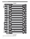
i) The sequence from Front to Rear is:
• Front Section
• 1" Low Water Cut-off Intermediate
• Three (3) Top Flue Outlet Intermediates
ii) The remaining intermediate sections are 3"
Tapped Intermediates or Plain Intermediates
as shown in Figure 2.8 and Figure 2.9.
15
Do not exceed the manufacturer’s torque
recommendations.
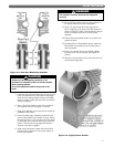
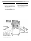
WARNING
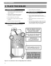
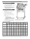
PLACE THE BOILER
Figure 2.7: Torque Specification/Procedure
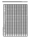
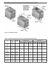
Figure 2.8: Section Positioning Numbering
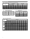
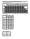
Table 2.1: Section Numbering Sequence
LC-04
LC-05
LC-06
LC-07
LC-08
LC-09
LC-10
LC-11
LC-12
LCE-13
LCE-14
LCE-15
LCE-16
LCE-17
LCE-18
LCE-19
LCE-20
LCE-21
LCE-22
LCE-23
LCE-24
Model
Place a Tapped Intermediate
Section at Position
(Numbered Rear to Front)
NA
NA
NA
NA
4
5
5
6
6
8
9
10
11
9
9
9
9
9, 16
9, 17
10, 18
10, 19