


A. GENERAL
1. Read the Burner Instruction Manual, supplied with
the boiler or with the burner if purchased separately.
Review applicable code requirements for burner and
fuel piping installations.
2. Install piping to allow removal of burner and access
to combustion chamber for cleaning or service.
B. INSTALL FUEL OIL PIPING
1. Place the fuel oil tank and install the piping in
accordance with NFPA-31 and all other applicable
codes.
2. General Guidelines for Oil Piping
a) Follow the guidelines in the Burner Manual for
sizing oil lines. Never use smaller than 1/2" OD
copper tubing.
b) Install manual shut-off valves on the suction line
at the burner and at the oil line entrance to the
building. If installing a shut-off valve on the
return line, you must provide an oil pressure
relief valve piped ahead of the shut-off valve and
discharged to the tank to prevent over-pressure
conditions.
c) Install a two-pipe oil distribution system when
possible. It will improve the reliability of the oil
delivery to the burner.
d) Use flare fittings when using copper tubing.
e) Provide an oil line filter in the suction line. Size
the filter for the suction gear capacity of the
burner oil pump if running a two-pipe system.
f) If burner is above the top of the fuel oil tank,
install a check valve on the oil suction line at the
burner to prevent oil from evacuating the line. If
burner is below the top of the tank, install an
anti-siphon device to prevent oil flow should the
oil line break.
C. INSTALL GAS SUPPLY PIPING
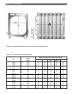
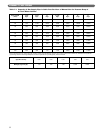
1. Size the piping as required by the National Fuel Gas
Code, ANSI Z223.1 or as required by local codes.
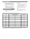
a) Use Table 7.1 for sizing of natural gas for a
system pressure drop of 0.3 inch water column.
2. The standard gas train is designed for a maximum
pressure of 1/2 psig (14 inches water column). Make
sure the system regulator will not allow a higher
pressure to the Gas Control Train under any
conditions.
3. The minimum gas supply pressure is listed on the
Burner Rating Plate. Make sure the system regulator
and the piping are sized and adjusted properly to
provide this pressure under all conditions.
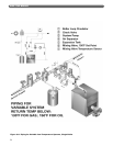
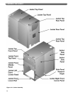
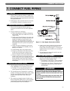
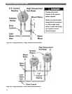
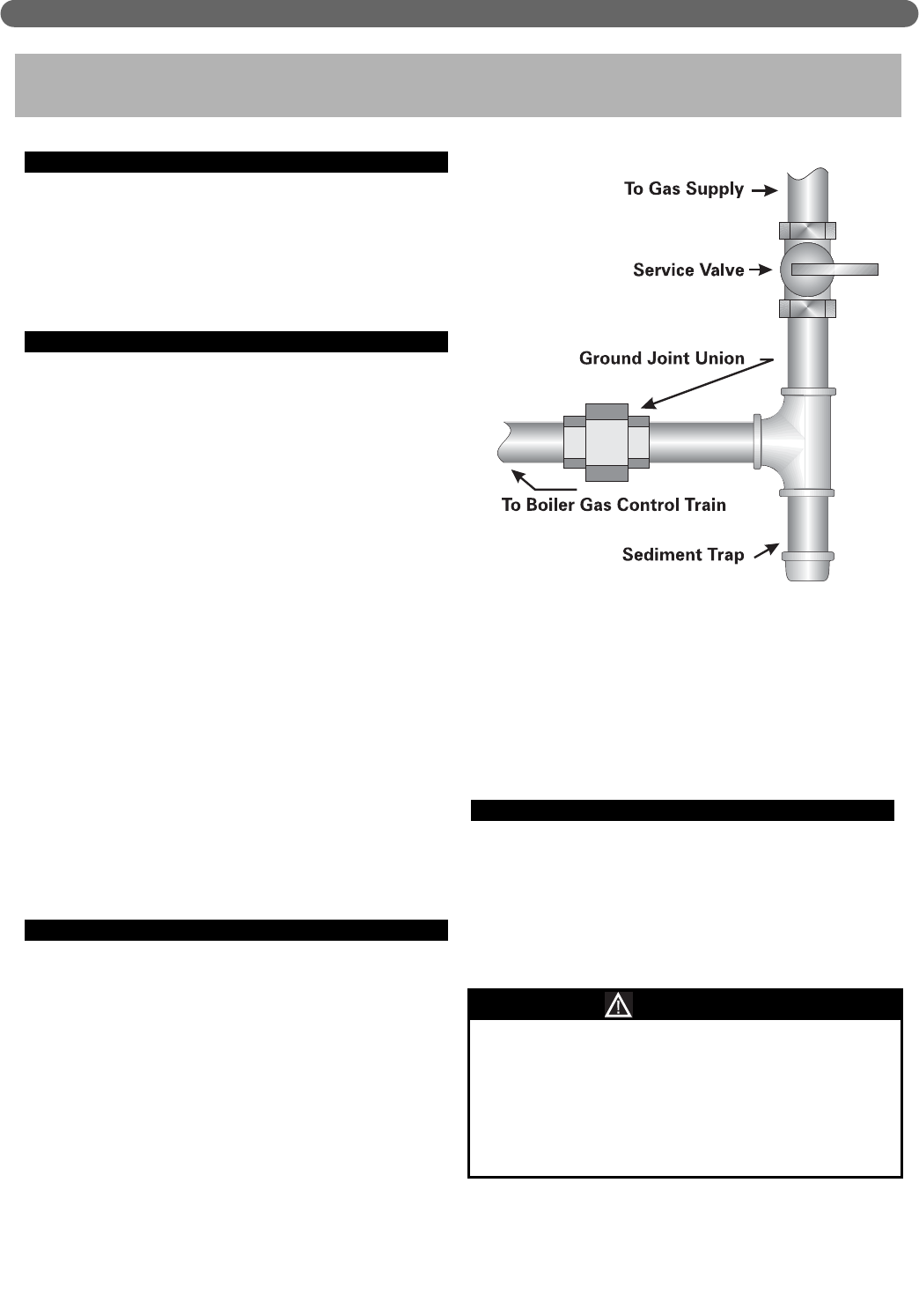
4. Install a Service Valve, Sediment Trap and Ground
Joint Union at the supply connection to the Gas
Control Train as shown in Figure 7.1. These are not
supplied with the boiler. Install them in accordance
with local codes.
5. Use only pipe joint compounds rated for use with
Liquefied Petroleum Gases.
D. TEST GAS SUPPLY PIPING
1. ISOLATE THE BOILER GAS CONTROL TRAIN
FROM THE SYSTEM DURING TEST:
a) Test pressure 1/2 psig or less – Close the Manual
Shut-Off Valve on the Boiler Gas Control Train.
b) Test pressure over 1/2 psig – Disconnect the gas
supply piping upstream of the Boiler Manual
Shut-Off Valve.
31
CONNECT FUEL PIPING
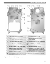
7. CONNECT FUEL PIPING
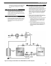
Figure 7.1: Gas Supply Connection to Boiler
Do not expose the Gas Control Train to excessive
pressure. The gas valves can be damaged. This could
result in explosion hazard and severe personal injury
or death.
Do not test gas supply piping with open flame. Use a
soap suds mixture brushed onto the pipe joints to
test for leaks.
WARNING