


29
VENTING
5. VENTING
Refer to Chapter 1, P
reinstallation, Section D. Chimney
or Vent for installation requirements. Refer to
Chapter 9, Star
ting the Boiler, Section C. Run Burner
Check Out
for damper settings and draft requirements.
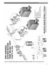
6. INSTALL THE BURNER
A. BURNER APPLICATION
1. Refer to Burner Spec and Data Sheets for the Oil
and Gas/Oil Burners pre-tested with Series LC
boilers.
2. Make sure the nozzle sizing and spray pattern match
those given in the spec and data sheets.
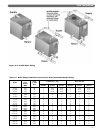
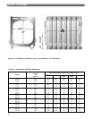
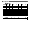
3. See Figure 6.1 and Table 6.1 for combustion
chamber dimensions.
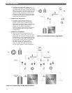
B. INSTALL BURNER MOUNTING PLATE
1. The Burner Mounting Plate is made to fit the burner
being used. Burners vary in bolt pattern for the
flange, burner tube diameter, insertion length and
near-tube configuration. Make sure the front plate is
correct for your burner if purchased separately from
the boiler.
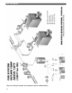
2. Remove the Burner Mounting Plate and Hardware
Bag from the crate.
3. Screw (7) 3/8"-16 x 2 1/4" studs into the holes in the
front section around the chamber opening.
4. Secure the Burner Mounting Plate to the front
section with the flat washers and hex nuts.
C. MOUNT THE BURNER
1. Remove the Burner from its crate. Read the burner
instructions.
2. Insert (4) 3/8"-16 x 1 1/4" studs supplied with Burner
Mounting Plate into the front plate holes.
3. Place the high temperature gasket on the burner
front plate and secure the burner to the front plate
with 3/8" flat washers and hex nuts.
4. If the burner is supplied with a pedestal, install it to
the burner per the Burner Manufacturer’s
Instructions. The pedestal provides additional
support and prevents the burner from sagging.