


A. PREPARE THE PARTS
1. Collect all the jacket cartons: Jacket Front & Back
Carton plus Jacket Side & Top Cartons. See
the Shipping List in the front of this manual for the
jacket cartons required. The cartons contain the
jacket parts and screws. The jacket panels are pre-
insulated.
2. Remove all needed knockouts from the jacket parts
before beginning assembly.
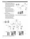
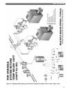
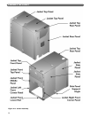
B. APPLY JACKET SIDES AND CORNERS
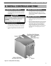
1. See Figure 4.2 for details.
2. The Side Panels can be used on either side of
the boiler.
3. Place the Jacket Side Panels on each side leaned
against the Boiler Sections.
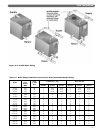
4. On Models LC-08 through LC-12, each side uses
two panels. Place the panels so the seam is centered
on the Tapped Intermediate Section. On LCE
models, place panels in the sequence shown in
Table 4.1.
5. On boilers with two or more Jacket Side Panels per
side, join the panels together with #10 x 1/2" sheet
metal screws. Also attach the Jacket Side Panel
Reinforcing Angle inside the jacket at the bottom of
the seam.
6. Attach the Left Front Corner Panel to the Left Side
Panel with #10 x 1/2" sheet metal screws.
7. Attach the Right Front Corner Panel to the Right
Side Panel with #10 x 1/2" sheet metal screws.
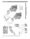
C. APPLY JACKET FRONT PANELS
1. Attach the Upper Front Panel to the Right and Left
Front Corner Panels with #10 x 1/2" sheet metal
screws.
2. Attach the Middle Front Panel and Lower Front Rail
in the same manner.
3. Position the Jacket Assembly with the front panels
pushed up against the front section. You will need
the jacket in this position to install the Burner Front
Plate.
D. APPLY JACKET REAR PANEL
1. Attach the Rear Jacket Panel to the Jacket Side
Panels with #10 x 1/2" sheet metal screws.
E. APPLY JACKET TOP PANELS
1. Attach the Top Front Panel to the Sides and Upper
Front Panel with #10 x 1/2" sheet metal screws.
2. Models LC-08 through LC-12 use two Jacket Top
Panels. Place them on top with the seam at the same
point as the side panels. Join them at their seam
with #10 x 1/2" sheet metal screws. On LCE models,
place panels in the sequence shown in Table 4.1.
3. Attach the Jacket Top Panel to the Jacket Top Front
Panel with #10 x 1/2" sheet metal screws.
4. Attach the Top Rear Panel to the Jacket Top Panel
with #10 x 1/2" sheet metal screws.
5. Finish by placing #10 x 1/2" sheet metal screws in
the remaining holes along the Jacket Top Panel
flanges, into the Jacket Side Panels.
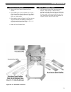
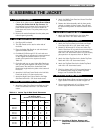
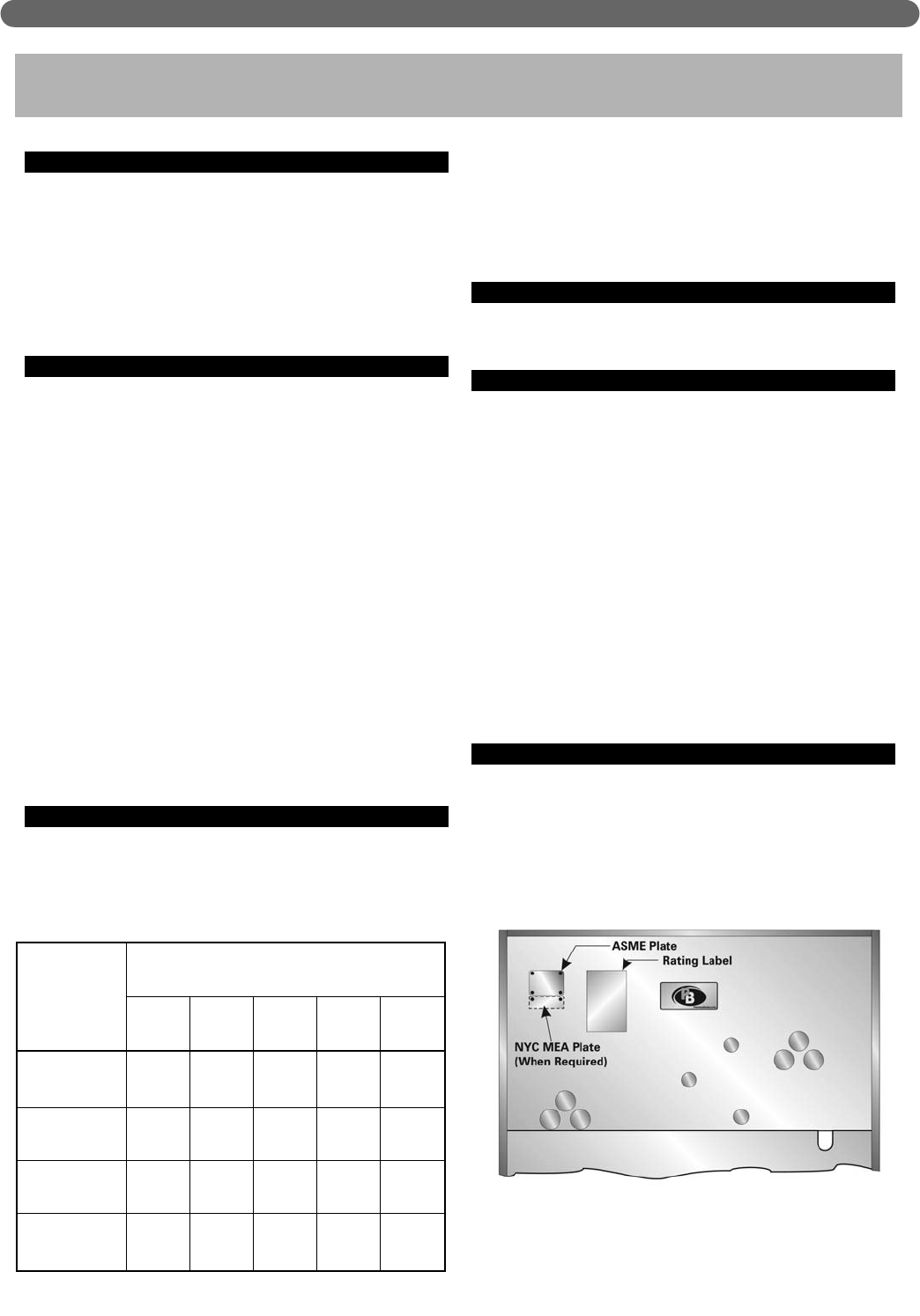
F. APPLY PLATES AND LABELS
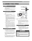
1. Mount Boiler Rating Plates and Agency Plates on the
Upper Jacket Front Panel as shown in Figure 4.1.
2. Secure metal plates with #6 x 1/4" sheet metal
screws. Apply all adhesive-backed labels.
27
4. ASSEMBLE THE JACKET
Figure 4.1: Location of Rating, Agency and
Instruction Plates on Jacket Front
Top Panel
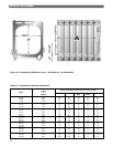
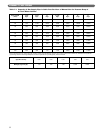
Table 4.1: Jacket Top & Side Panel Placement
LCE-13
LCE-14
LCE-15
LCE-16
LCE-17
LCE-18
LCE-19
LCE-20
LCE-21
LCE-22
LCE-23
LCE-24
Model
Locate Jacket Top and Side Panels in
the Position Below
(Numbers are from Rear to Front)
5
(Front)
432
1
(Rear)
–
–
–
–
–
–
–
E
E
E
E
E
–
–
–
–
E
E
E
A
A
B
B
C
E
E
E
E
A
B
C
A
B
B
B
B
B
B
B
C
B
B
B
B
B
B
B
B
A
B
C
C
B
B
B
B
B
B
C
C
ASSEMBLE THE JACKET