


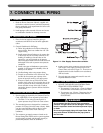
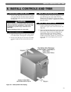
A. INSTALL SAFETY RELIEF VALVE
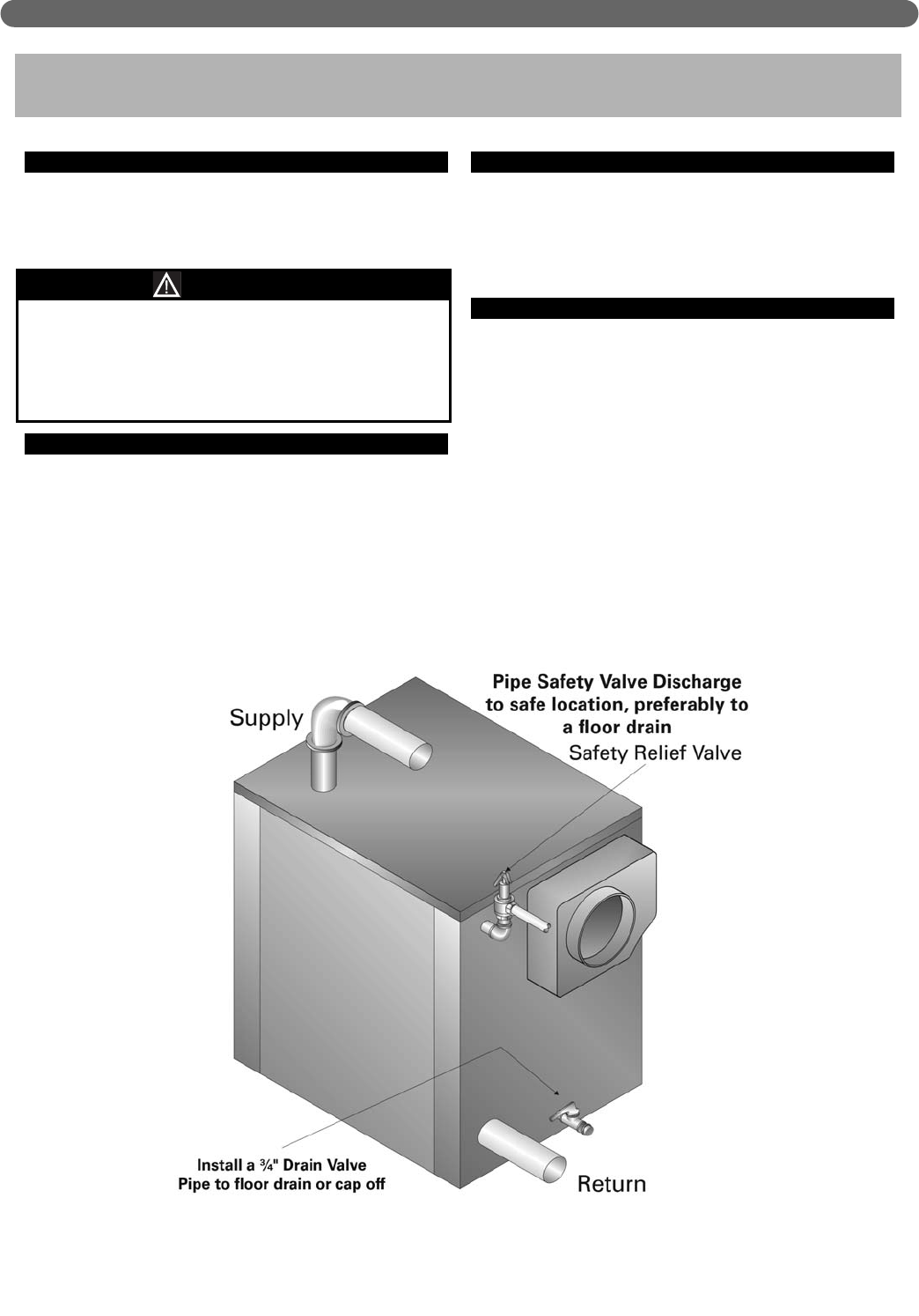
1. Pipe the Safety Relief Valve off of the 2-1/2" tapping
at the upper left side of the Rear Section. Make sure
the relief valve sizing meets local code requirements.
See Figure 8.1.
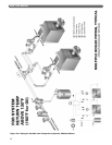
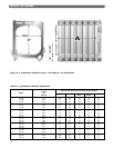
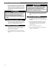
B. INSTALL DRAIN VALVE
1. Install a 3/4" drain valve in the lower center tapping
in the Rear Section. See Figure 8.1 and Figure 8.2.
2. Pipe the valve discharge to a floor drain if available
or apply a nipple and cap to close off when not in
use.
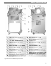
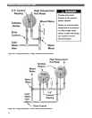
C. INSTALL LOW WATER CUTOFFS
1. See Figure 8.2 for the locations of tappings for probe
type and float type low water cutoffs. The Front
Section has a 3/4" tapping for a probe type control.
The Rear Section has two 1" tappings for mounting a
float type control.
D. INSTALL CONTROLS & TRIM
1. Install the Temperature-Pressure Gage in the 1/2"
tapping at the upper center of the Front Section. See
Figure 8.2.
2. Mount the Operating Temperature Limit Control bulb
well in the Coil Cover Plate at the upper right of the
Front Section. Place the well in the right side 3/4"
control tapping of the cover plate if a Tankless
Heater is not installed there. If a tankless heater is
installed at this location (Position 2), mount the well
in the center 3/4" control tapping of the coil. See
Figure 8.2.
33
INSTALL CONTROLS AND TRIM
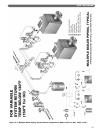
8. INSTALL CONTROLS AND TRIM
Figure 8.1: Safety Relief Valve Piping
Pipe the discharge of the Safety Relief Valve(s) away
from any traffic area, preferably to a floor drain. This
is necessary to prevent injury should the valve
discharge.
Pipe the discharge full size of valve outlet.
CAUTION