


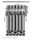
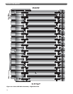
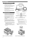
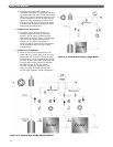
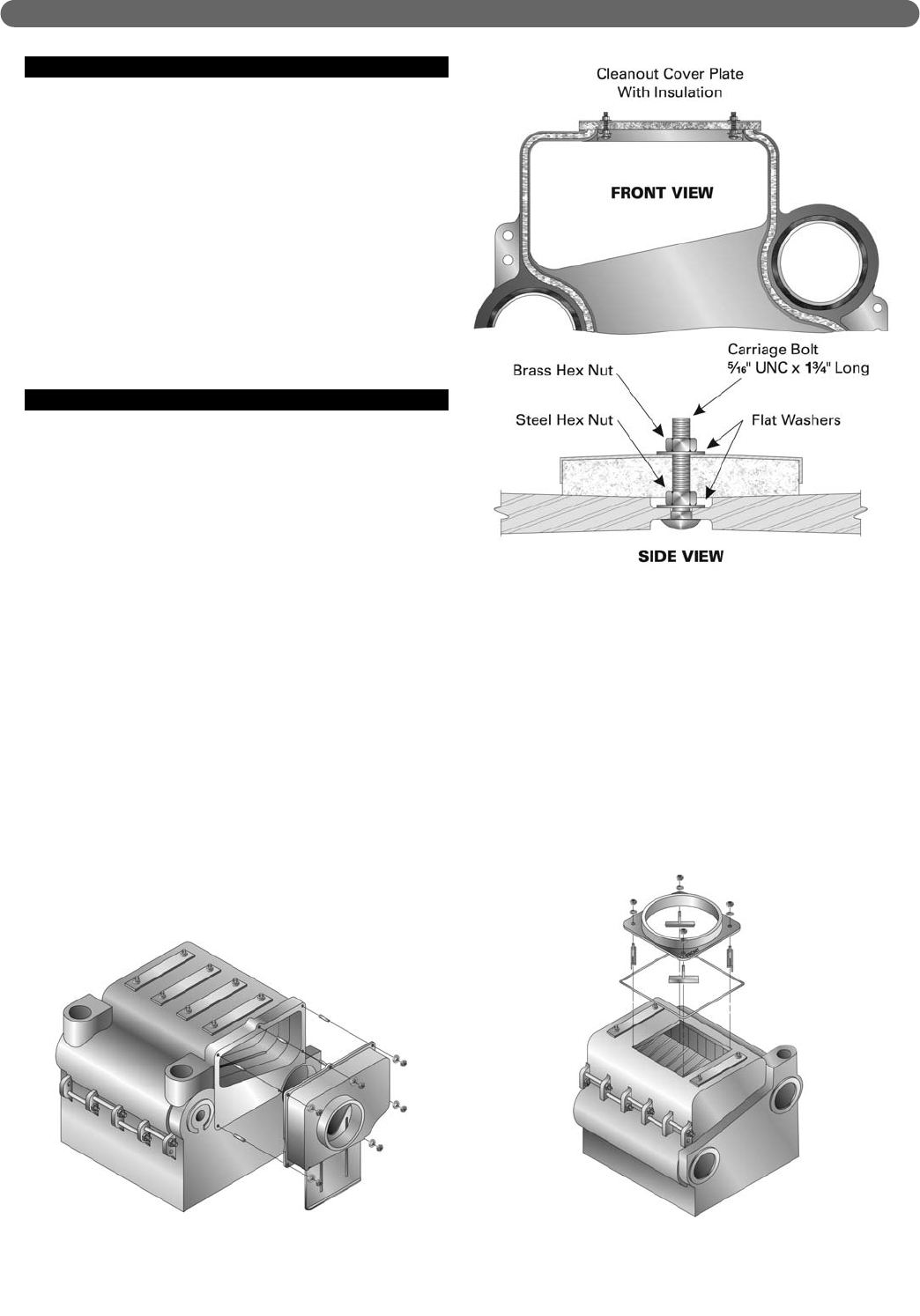
F. APPLY CLEANOUT COVER PLATES
1. Apply the Cleanout Cover Plates on the tops of the
section joints as shown in Figure 2.11.
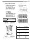
2. Pre-assemble a steel flat washer and steel nut on the
carriage bolts. Place a carriage bolt into each side of
the cleanout opening as shown in the figure.
3. Tighten the lower nut securely.
4. Press the Cleanout Plate with insulation over the
protruding carriage bolts until the insulation lays
flush against the cast iron.
5. Apply a flat washer and brass nut to the carriage
bolt. Draw the brass nuts down until the insulation
presses firmly against the iron.
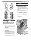
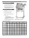
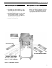
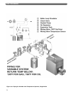
G. INSTALL FLUE COLLAR
1. (LC) Remove the Flue Collar and Rear Observation
Door Assembly from the LC Rear Flue Box Carton.
(LCE)Remove the Top Flue Outlet Plate, the Rear
Flue Cover Plate and the Rear Observation Door
Assembly from the LCE Top Flue Outlet Carton.
2. (LC) Attach the Flue Collar to the Back Section with
5/16" x 1-1/2" studs, flat washers and hex nuts
supplied. See Figure 2.12.
(LCE) Attach the Rear Flue Cover Plate to the Rear
Section with 5/16" x 1-1/2" studs, flat washers and
nuts supplied.
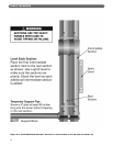
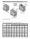
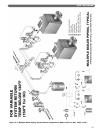
3. (LCE) Apply spray adhesive (supplied in Section
Assembly Kits) to the rope groove on the bottom of the
Top Flue Outlet Plate. Place the high temperature rope
seal in the groove, overlapping at the ends for a good
seal.
a) Place the plate over the opening provided by the
three top flue intermediate sections at the front of
the boiler. NOTE: Top flue outlet plate is marked
“FRONT▼” for proper orientation.
b) Secure the plate and compress using the 3/8" tie
down assembly, nuts and washers provided. See
Figure 2.13.
c) Inspect the finished seal, particularly where the
plate crosses the section joints.
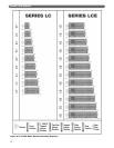
d) The correct Top Flue Outlet Plate for the LCE
boiler is:
• LCE-13 thru LCE-17 use the 14" flue opening,
part number LCE-5007, Carton D
• LCE-18 thru LCE-24 use the 16" flue opening,
part number LCE-5007-1, Carton E
4. Attach the Rear Observation Door to the Rear
Section with four (4) 5/16"-18 x 3/4" hex head bolts
provided.
18
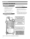
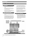
PLACE THE BOILER
Figure 2.12: Rear Flue Collar Attachment Figure 2.13: Top Flue Collar Attachment
Figure 2.11: Install Cleanout Cover Plates