


6
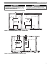
9. Pressure Relief Valve: The boiler pressure relief valve
is factory installed into the right side boiler manifold
(inside the jacket). Pipe the discharge of the relief
valve to within 12" of the floor and close to a floor
drain. Provide piping that is the same size or larger
than the relief valve outlet.
10. Circulator: The boiler circulator is to be sized to
overcome the pressure drop of the system while
providing the flow required by the boiler.
a. If the boiler is piped in a secondary loop of a
primary/secondary heating system, the circulator
will need only to overcome the resistance of the
boiler and any fittings in that loop.
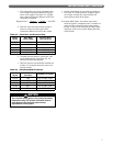
b. The circulator should be sized based on the net
output of the boiler. The Table 3.2 shows the
Boiler Output as reported to the Hydronics
Institute division of GAMA. These values are
based on a pickup factor of 1.15.
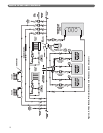
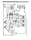
WATER PIPING AND CONTROLS
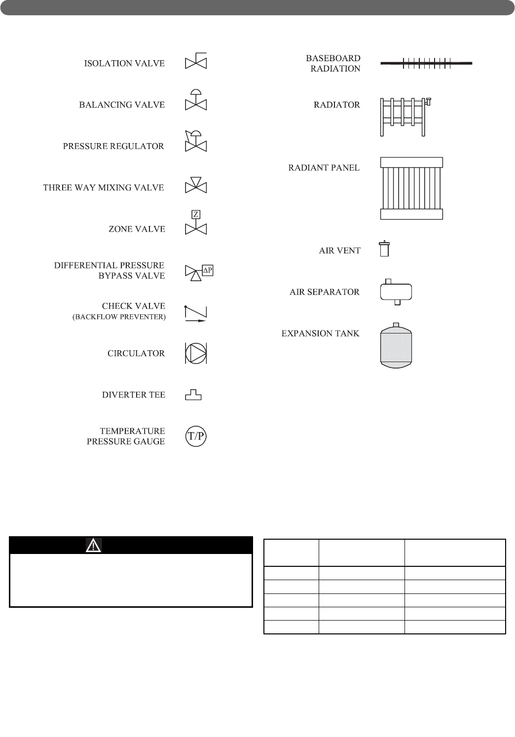
Table 3.2 – Boiler Inputs and Outputs
Boiler
Model
Boiler Input
(Btu/hr [kW])
Net I=B=R Output
(Btu/hr [kW])
PI-T50 50,000 (14.7) 40,000 (11.7)
PI-T80 80,000 (23.4) 64,000 (18.8)
PI-80 80,000 (23.4) 64,000 (18.8)
PI-140 140,000 (41.0) 112,000 (32.8)
PI-199 199,000 (58.3) 159,000 (46.6)
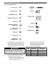
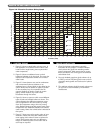
Figure 3.1: Piping Symbol Key
Pipe the discharge of the relief valve as close as
possible to the floor and away from high traffic areas.
Pipe the discharge to a floor drain. Failure to do so
may result in personal injury and/or property damage.
CAUTION