


8
D. SYSTEM PIPING
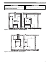
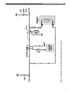
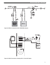
1. Figure 3.3 shows a single boiler with two zones. In
this application, the Peerless Partner indirect water
heater and the single heating zone require similar
water temperature.
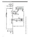
2. Figure 3.4 shows an additional zone in which
baseboard radiation is the heat load. This zone also
requires water temperatures similar to the indirect
water heater.
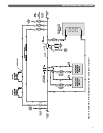
3. Figure 3.5 shows diverter tees used in combination
with conventional hydronic radiators on an
additional zone. A second boiler is also added to the
system. Notice that the boilers are piped in parallel
on the secondary loop. It is important that the
common headers are sized to match the system
piping. Smaller headers may result in flow
fluctuations through the boilers.
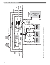
4. Figure 3.6 shows a system in which several different
types of loads and multiple boilers are shown. This
system illustrates how different temperature zones
can be supplied from the same source by mixing
down the temperature using a three way mixing
valve. Radiant flooring typically requires much lower
temperatures than baseboard radiation and indirect
water heating. Notice that a third boiler is included in
this system.
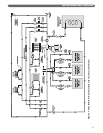
5. Figure 3.7 shows zone valves used in place of zone
circulators. Notice that this system utilizes reverse
return piping which makes it easier to balance the
system. If the heating zones are very different in
length, the balancing valves on the return side of
each loop are required.
E. FREEZE PROTECTION
1. Glycol for hydronic applications is specially
formulated for this purpose. It includes inhibitors
which prevent the glycol from attacking metallic
system components. Make certain that the system
fluid is checked for the correct glycol concentration
and inhibitor level.
2. Use only inhibited propylene glycol solutions of up
to 50% by volume. Ethylene glycol is toxic and can
chemically attack gaskets and seals used in hydronic
systems.
3. The antifreeze solution should be tested at least once
per year and as recommended by the antifreeze
manufacturer.
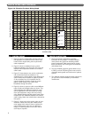
WATER PIPING AND CONTROLS
0
1
2
3
4
5
6
7
8
9
10
11
12
13
14
15
16
17
18
19
20
21
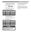
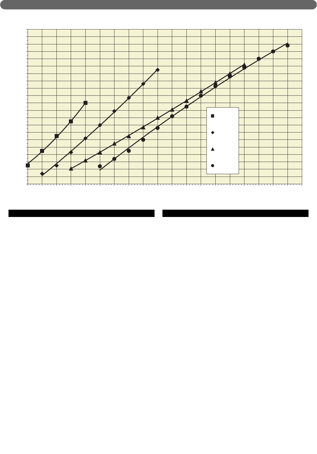
3 4 5 6 7 8 9 10 11 12 13 14 15 16 17 18 19 20 21 22
Flow Rate (GPM)
Pressure Drop (Feet of Head)
PI-T50
PI-T80/80
PI-140
PI-199
Figure 3.2: Pinnacle Circulator Sizing Graph