


19
A. GENERAL
1. Install the boiler venting system in accordance with
these instructions and with the National Fuel Gas
Code, ANSI Z223.1/NFPA 54, CAN/CGA B149,
and/or applicable provisions of local building codes.
2. This boiler is a direct vent appliance and is listed as a
Category IV appliance with Underwriters
Laboratories, Inc.
B. APPROVED MATERIALS FOR EXHAUST
VENT AND INTAKE AIR PIPE
1. Use only Non Foam Core venting material. The
following materials are approved for use as vent pipe
for this boiler:
a. Non Foam Core PVC (Polyvinyl Chloride) Pipe
conforming to ASTM D-1784 Class 12454-B
(formerly designated Type 1, Grade 1).
b. Non Foam Core CPVC (Chlorinated Polyvinyl
Chloride) Pipe conforming to ASTM D-1784
Class 23447-B (formerly designated Type IV,
Grade 1).
c. Non Foam Core ABS (Acrylonitrile-Butadiene-
Styrene) Pipe conforming to ASTM D3965
Class 3-2-2-2-2.
2. Cellular foam core piping may be used on air inlet
piping only. Never use cellular foam core material for
exhaust piping.
C. EXHAUST VENT / AIR INTAKE PIPE
LOCATION
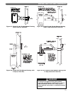
1. Determine exhaust vent location:
a. The vent piping for this boiler is approved for
zero clearance to combustible construction.
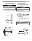
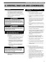
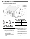
b. See Figure 5.1 for an illustration of clearances for
location of exit terminals of direct-vent venting
systems.
c. This boiler vent system shall terminate at least 3
feet (0.9 m) above any forced air intake located
within 10 ft (3 m). Note: this does not apply to
the combustion air intake of a direct-vent
appliance.
d. Provide a minimum of 1 foot distance from any
door, operable window, or gravity intake into any
building.
e. Provide a minimum of 1 foot clearance from the
bottom of the exit terminal above the expected
snow accumulation level. Snow removal may be
necessary to maintain clearance.
f. Provide 4 feet horizontal clearance from electrical
meters, gas meters, gas regulators, and relief
equipment. In no case shall the exit terminal be
above or below the aforementioned equipment
unless the 4 foot horizontal distance is
maintained.
g. Do not locate the exit terminal over public
walkways where condensate could drip and/or
freeze and create a nuisance or hazard.
h. When adjacent to a public walkway, locate exit
terminal at least 7 feet above grade.
i. Do not locate the exit termination directly under
roof overhangs to prevent icicles from forming.
j. Provide 3 feet clearance from the inside corner
of adjacent walls.
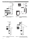
2. Determine air intake pipe location.
a. Provide 1 foot clearance from the bottom of the
air inlet pipe and the level of maximum snow
accumulation. Snow removal may be necessary
to maintain clearances.
b. Do not locate air intake pipe in a parking area
where machinery may damage the pipe.
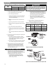
c. Maximum distance between air intake and
exhaust vent is 6 feet (1.8 m). Minimum distance
between exhaust vent and air intake on single
Pinnacle is 8" (0.2 m) center-to-center. Minimum
distance between vents and intakes on multiple
Pinnacles is 8" (0.2 m) center-to-center. See
Figure 5.2.
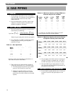
VENTING, INLET AIR AND CONDENSATE
5. VENTING, INLET AIR AND CONDENSATE
This vent system will operate with a positive
pressure in the pipe. Do not connect vent connectors
serving appliances vented by natural draft into any
portion of mechanical draft systems operating under
positive pressure.
WARNING
Follow these venting instructions carefully. Failure to
do so may result in severe personal injury, death, or
substantial property damage.
WARNING
Do not use Foam Core Pipe in any portion of the
exhaust piping from this boiler. Use of Foam Core
Pipe may result in severe personal injury, death, or
substantial property damage.
WARNING