


21
4. The minimum combined equivalent length is 16
equivalent feet.
5. The maximum combined equivalent length can be
extended by increasing the diameter of the vent
pipe. However, the transitions should begin a
minimum of 15 equivalent feet from the boiler.
a. Transitions should always be made in vertical
sections of pipe to prevent the condensate from
pooling in the vent pipe.
b. Use a 3" x 2" reducing coupling to transition from
the PI-T50 and PI-T80 boiler connections to a 3"
vent.
c. Use a 4" x 3" reducing coupling to transition from
the PI-80, PI-140, and PI-199 boiler connections
to 4" vent.
d. The maximum equivalent length for the
increased diameter vent pipes is 125 feet.
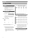
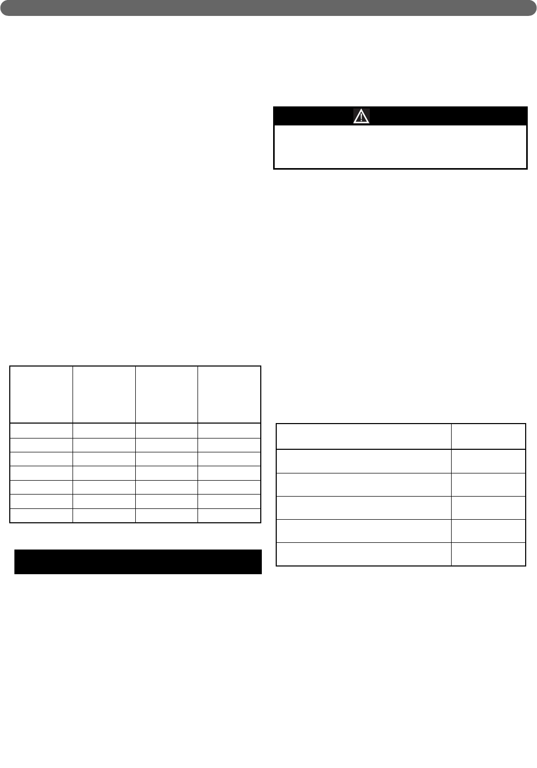
e. If the transition occurs at a distance greater than
15 equivalent feet from the boiler, the maximum
equivalent length will be reduced. See Table 5.2.
Standard Vent Pipe is 2” and Oversized Vent
Pipe is 3” for PI-T50 and PI-T80. Standard Vent
Pipe is 3” and Oversized Vent Pipe is 4” for PI-
80 through PI-199.
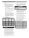
E. EXHAUST VENT AND AIR INTAKE PIPE
INSTALLATION
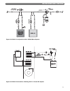
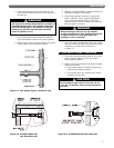
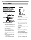
1. On the PI-T50 and PI-T80 the 2" exhaust vent
connection is located on the top, right side of the
boiler and the air intake is on the top, left side. See
Figure 10.1. The air intake connection is intended
for a slip fit. No sealant or adhesive is required.
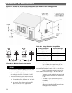
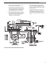
2. On the PI-80, PI-140, and PI-199 Boilers the 3”
exhaust vent connection is located on the rear of the
boiler and the air intake is higher and toward the left
side when the boiler is viewed from the front. See
Figure 10.2. The air intake connection is intended for
a slip fit. No sealant or adhesive is required.
3. Use only solid PVC, CPVC, or ABS schedule 40 or
80 pipe. FOAM CORE PIPING IS NOT APPROVED.
4. Remove all burrs and debris from joints and fittings.
5. All joints must be properly cleaned, primed, and
cemented. Use only cement and primer approved for
use with the pipe material. Cement must conform to
ASTM D2564 for PVC or CPVC pipe and ASTM
D2235 for ABS pipe.
6. Horizontal lengths of exhaust vent must slope back
towards the boiler not less than ¼" per foot to allow
condensate to drain from the vent pipe. If the vent
pipe must be piped around an obstacle that causes a
low point in the pipe, a drain pipe must be
connected to allow condensate to drain.
7. All piping must be fully supported. Use pipe hangers
at a minimum of 4 foot intervals to prevent sagging
of the pipe where condensate may form.
8. Do not use the boiler to support any piping.
9. A screened straight coupling is provided with the
boiler for use as an outside exhaust termination.
10. A screened inlet air tee is provided with the boiler to
be used as an outside intake termination.
11. The following are optional intake air/exhaust vent
terminations available from your PB Heat, LLC
distributor for use with Pinnacle boilers.
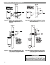
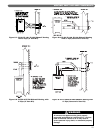
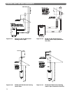
12. Refer to Figure 5.3 to 5.10 for sidewall venting and
Figures 5.11 to 5.14 for vertical venting.
VENTING, INLET AIR AND CONDENSATE
Description
Stock
Code
2" PVC Concentric Vent Termination Kit 91469
3" PVC Concentric Vent Termination Kit 91403
2" Stainless Steel Vent Termination Kit 91465
3" Stainless Steel Vent Termination Kit 91402
4" Stainless Steel Vent Termination Kit 91401
Table 5.3: Vent Termination Kits
All joints of positive pressure vent systems must be
sealed completely to prevent leakage of flue products
into the living space.
WARNING
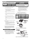
Transition
Point
(ft from
boiler)
TEL of
Standard 2”
or 3” Vent
Pipe (ft)
TEL of
Oversized 3”
or 4” Vent
Pipe (ft)
Maximum
TEL of all
Vent Pipe (ft)
15 30 95 125
20 40 77-1/2 117-1/2
25 50 60-1/2 110-1/2
30 60 43 103
35 70 26 96
40 80 8-1/2 88-1/2
None 85 0 85
Table 5.2: Maximum Equivalent Vent Length for
Oversized Vent Pipe
TEL = Total Equivalent Length