17
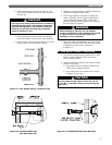
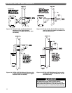
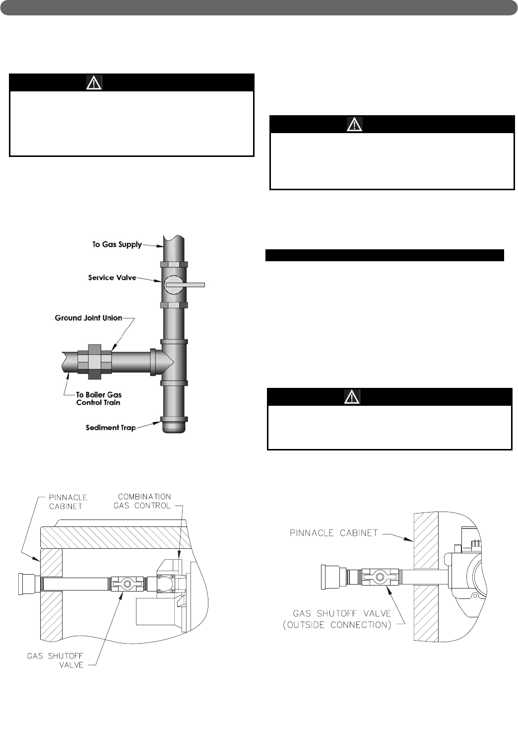
2. Install a sediment trap as shown in Figure 4.1. Be
sure to allow clearance from the floor for removal of
the pipe cap.
3. Install a ground joint union between the sediment
trap and the boiler to allow service of the appliance.
4. Install a service valve as shown in Figure 4.1 to allow
the gas supply to be interrupted for service.
5. Maintain a minimum distance of 10 feet between the
gas pressure regulator and the boiler.
6. Check all gas piping for leaks prior to placing the
boiler in operation. Use an approved gas detector,
non-corrosive leak detection fluid, or other leak
detection method. If leaks are found, turn off all gas
flow and repair as necessary.
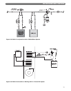
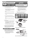
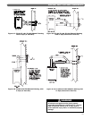
7. Figure 4.2 and 4.3 are illustrations of the gas shutoff
valve for the Pinnacle Boiler. This valve is to be used
in addition to the gas service valve shown
in Figure 4.1.
D. GAS SUPPLY PIPING - OPERATION
1. The gas line must be properly purged of air to allow
boiler to operate. Failure to do so may result in
burner ignition problems.
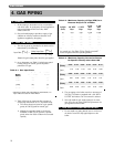
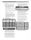
2. Table 4.4 shows the maximum and minimum supply
pressure to the boiler.
a. Gas pressure below the minimum pressure may
result in burner ignition problems.
b. Gas pressure above the maximum may result in
damage to the gas valve.
GAS PIPING
Do not subject the gas valve to more than 1/2 psi
(13.5" W.C.) of pressure. Doing so may damage the
gas valve.
CAUTION
Use a pipe joint sealing compound that is resistant to
liquefied petroleum gas. A non-resistant compound
may lose sealing ability in the presence of this gas,
resulting in a gas leak. Gas leaks may potentially
cause an explosion or fire.
WARNING
When checking for leaks, do not use matches,
candles, open flames or other methods that provide
an ignition source.This may ignite a gas leak
resulting in a fire or explosion.
WARNING
Figure 4.1: Gas Supply Piping – Sediment Trap
Figure 4.2: PI-80/PI-140/PI-199
Gas Valve Shut Off
Figure 4.3: PI-T50/PI-T80 Gas Valve Shut Off


