


DATA-LINC GROUP
33
DDAA1000/SRM User Guide
PN 161-09981-002C
rev 8/04
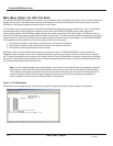
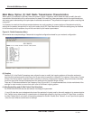
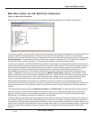
Main Menu Option (4): Show Radio Statistics
Option (4) in the main menu allows the user to view data transmission statistics, which have been gathered by the
Transceiver during the most recent session. Statistics are gathered during each data link and are reset when the next link
begins. Ideally, noise levels should be below 30, and the difference between the average signal level and average noise level
should be 15 or more. High noise levels tend to indicate other sources of RF interference, while low signal levels indicate a
weak link. The “Local” stats are the statistics that are being gathered by the modem you are connected to while “Remote1,
Remote2, and Remote3” are the stats of the repeater(s) that the modem you are attached to is using to get back to the
master modem. The following sections provide information useful to the process of troubleshooting and improving radio links.
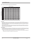
Average Noise Level
The average noise level indicates the level of background noise and interference at this modem and at each of the modems
used as repeaters in the link. The number is an average of the noise levels measured at each frequency in the modems’
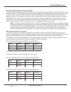
frequency hop table. The individual measurement values at each frequency hop channel are shown in the frequency table.
The frequency table is accessed by pressing the ENTER key on the computer when the radio statistics menu is displayed.
Average noise levels will typically fall in the range of 15 to 30. Average noise levels significantly higher than this are an
indication of a high level of interference that may degrade the performance of the link. High noise levels can often be improved
with bandpass filters, antenna placement or antenna polarization. Please contact Data-Linc Group for more information.
Average Signal Level
The average signal level indicates the level of received signal at this modem and at each of the modems used as repeaters in
the link. For each of these, the signal source is the modem that transmits to it. The number is an average of the received
signal levels measured at each frequency in the modem’s frequency hop table. The individual measurement values at each
frequency hop channel are shown in the frequency table. The frequency table is accessed by pressing the ENTER key on
the computer when the radio statistics menu is displayed.
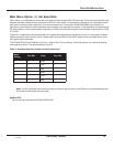
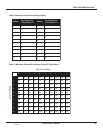
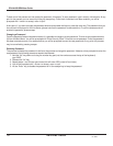
For a reliable link, the average signal level should be at least 30 higher than the average noise level reading. The table below
provides an approximate conversion of average signal level values into the more common dBm (decibel milliwatts). Low
Average Signal Levels can often be corrected with higher gain antennas, antenna placement, and use of repeaters. Contact
Data-Linc Group for more information.
leveLlangiSegarevA1494066658
mBdnileveL011-001-06-08-07-
Overall Rcv Rate (%)
The Overall Rcv Rate measures the percentage of data packets that were successfully transmitted from the master to the
remote on the first attempt without requiring retransmission. A number of 75 or higher indicates a robust link that will provide
very good performance even at high data transmission rates. A number of 25 or lower indicates a weak or marginal link that
will provide lower data throughput. An Overall Rcv Rate of 100% will provide approximately 100 Kbaud of bandwidth with an
RF data rate of 3 (Radio Transmission Parameters Menu) and approximately 150 Kbaud of bandwidth with an RF Data Rate
of 2. These numbers are reduced approximately 50% if there are one or more repeaters in the network.