


DATA-LINC GROUP
12
PN 161-09981-002C
rev 8/04
DDAA1000/SRM User Guide
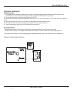
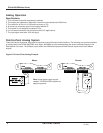
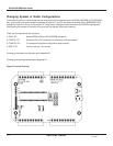
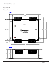
Changing System or Radio Configurations
To access the system or radio setups the user must remove all connectors from the DDAA1000/SRM or DD1000/SRM,
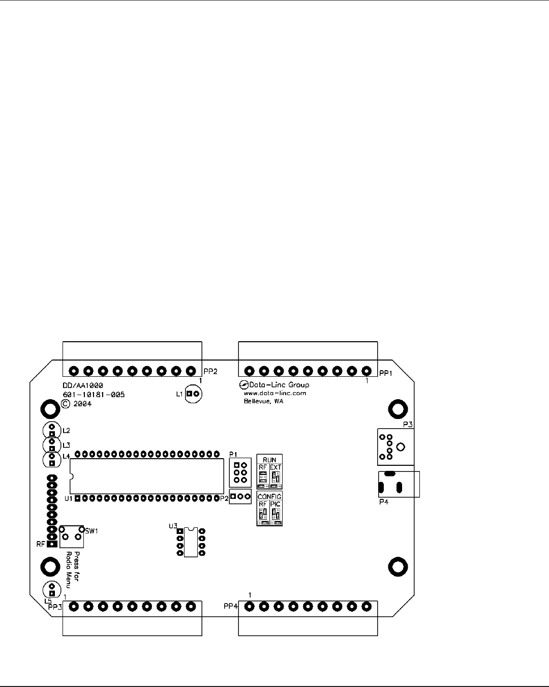
then remove the cover and change the jumpers at location P1 and P2, and add a serial data cable (SRM6200E-SLC),
supplied by Data-Linc Group, to connector P3. These jumper settings must be returned to the RUN/RF settings after
reconfiguring the system or the radio or the units will not operate. See layout drawing.
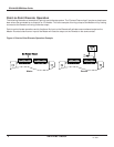
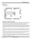
There are 4 configurations of the jumpers.
1. RUN / RF Normal DDAA/1000 and DD1000/SRM operations
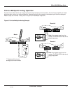
2. CONFIG / RF Serial port P3 to PC (computer) to access the radio parameters
3. CONFIG / PIC To reprogram the system configuration setup memory
4. RUN / EXT Factory use only - do not use
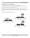
If changing the system configuration go to Appendix B.
If changing the radio parameters go to Appendix C.
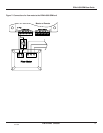
Figure 9: Layout Drawing