


DATA-LINC GROUP
17
DDAA1000/SRM User Guide
PN 161-09981-002C
rev 8/04
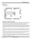
Appendix B
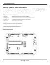
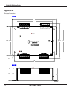
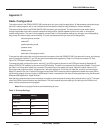
Figure 10: PCB Layout
DDAA1000 - DD1000 Configuration
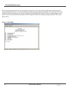
The system configuration parameters are stored in an EEprom memory. This memory can only be changed by the onboard
microprocessor using serial commands via port P3. The easiest method is to use the Data-Linc Group program provided
with the master unit, to be run on a PC. If the program is missing contact Data-Linc Group Technical Support.
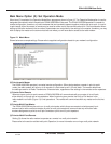
A DDAA1000/DD1000 system is normally factory pre-configured. Changes to the system are possible, but it is
recommended that the user perform this function under direction of Data-Linc Group Technical Support personnel. If the
utility program is missing, it is possible to change the setting using a PC with a terminal program, but Data-Linc Group help
must be used as the system setting can be confusing. An internal knowledge of the microprocessor operation is vital to
understand how to set the system memory. Setting any of the system configuration parameters wrong will make a broken
system.
To access the system configurations the user must remove all connectors from the DDAA1000/DD1000, the remove the
cover, and change a set of jumpers at location P1 and P2 and add a serial data cable (SRM6200E-SLC) available from
Data-Linc Group to connector P3. See Figure 10, PCB layout drawing. Use the CONFIG-PIC layout as shown on the PCB
drawing.
To change the system configuration, set the P1 and P2 jumpers as shown on the layout drawing. Use the CONFIG-RF
layout as shown on the PCB drawing. The dark lines represent the three small jumpers. Then insert the Data-Linc Group
serial cable into connector P3 located next to the power connector. Attach the serial cable to a PC.
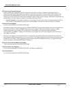
Remember that there are two different part numbers for Masters and Remotes. They contain different firmware. A Master
cannot be made into a Remote, and a Remote cannot be made into a Master. However, either a Master or Remote can
have the ability to reprogram an EEprom from either a Master or Remote. This involves removing and replacing the EEprom
(U3) on the PCB. Not recommended for most users.