


DATA-LINC GROUP
18
PN 161-09981-002C
rev 8/04
DDAA1000/SRM User Guide
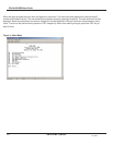
If you have the Data-Linc Group PC program DDAAEEprom.exe it is designed to run in Windows. Load the program
DDAAEEprom.exe into your PC. Start the program. When the system layout window appears fill in the following
information:
1. Select Model DDAA or DD1000 with mouse click.
2. The PCs Comm (serial port) number 1 or 2 with a mouse click.
3. The serial Baud rate that the DDAA1000/DD1000 uses to talk to the radio module. This is not the connection speed to
the computer. This must match the Baud rate set in the radio module. The factory default for the radio module is 9600.
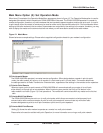
4. Select System Configuration as either a Point-to-Point (one remote) or a Multipoint system (more than one remote) with
mouse click.
5. Select this unit is a Master or a Remote. This must agree with the code in the microprocessor. You can not change a
units Master/Remote type in the field.
6. The number of remotes if a Multipoint System.
7. If programming a Multipoint Remote select Remote ID or address you are changing. Remotes have addresses of zero(0)
to seven(7).
If the unit is a DD1000 click on the “Make an EEprom” button and follow the prompting instructions on the screen. . If any
previous setting are in conflict or you have not made a needed selection, the parameter will highlight to red. To proceed,
correctly fill in the parameter and click the “Make an EEprom” again.
The program will write several characters into the boxes at the bottom, and lower left of the display. These are the serial
commands containing the system parameters that are sent and received by the DDAA1000/DD1000 units.
Repeat this procedure once for each Master, and once for each Remote in the system. Make sure you change the address
for each Remote.
Each time the program finished making an EEprom, and if a printer is connected to the computer, you can click on the
PRINT button on the lower right corner to make a record of the system configuration. It will be handy later when you call
Data-Linc Group to try to figure out why your system won’t work.
When done, click on the EXIT button at the lower right corner of the window.
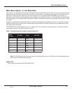
If the unit is a DDAA1000
, fill in the Master DDAA chart. The ‘X’s in the chart are the system configuration. The Remotes
ID is the left side of the chart, the IN columns are the 4-20ma input numbers on the Masters connectors. Assign analog
input(s) to each Remote by clicking the cursor on the row (address) and column (input #) for the Remote and the input to
use. This will toggle the ‘X’ on or off. Assign the analogs for Remote zero (0) first, then Remote one (1), Remote two (2) thru
seven (7). If there are less than seven remotes toggle the remaining ‘X’s off. The default for the system is all 8 analog inputs
assigned to Remote zero( 0).
The program will not allow the user to assign analog inputs in a wrong order. If a wrong assignment is made then program
removes the ‘X’ selection. The maximum number of rows used is set by the number of remotes selected in step 6 above.
Do not leave any columns blank if a later column has an ‘X’. The data transfer from Master to Remote will stop when a
blank filed is reached. Blank columns at the right side of the table are okay. Not all analog inputs need to be assigned, just
no orphaned –empty columns.