


Wiring the Electrical System
6.1 Before You Begin
The Oasis™ Heating Module and its electrical Control Board are pre-
wired and have been thoroughly tested together as a unit.
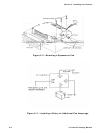
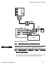
To review the wiring system for the Oasis™ Heating Module, refer
to the wiring diagram at the end of this Section 6, Figure 6-1:
System Wiring.
All electrical connections and wiring must comply with normally-
accepted 12 VDC and 120 VAC wiring practices, local regulations,
and ABYC/RVIA standards. Only a qualified electrical installer
should complete the wiring. All field wiring is to be in accordance
with CSA Standard C22.1, Canadian Electrical Code Part l or the
National Electrical Code, ANSI/NFPA 70.
Section
6
! WARNING
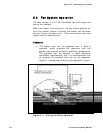
6.2 12 VDC
The following apply to the 12 VDC connections for the Oasis™
Heating Module:
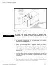
• There is one paired set of 12 VDC electrical connections on the
top right of the Oasis™ Heating Module. They consist of the
primary DC positive (red) and negative (black) connection and
are 14 gauge stranded copper wires.
Primary DC power should originate from a dedicated connection on
the house battery bank. A 20 amp fuse or breaker must be
included close to and inline from the battery to the positive (red)
connection on the Oasis™ Heating Module. The primary power wire
gauge must be sized to permit no more than a 3% voltage drop
from the battery to the Oasis™ Heating Module.
! WARNING
• A properly-shielded power system is required for safe, trouble-
free operation.
International Thermal Research 6-1