


Section 3, Installing the Exhaust System
5 Connect the flexible air-intake tubing (2” I.D.) to the air-
intake fitting on top of the heater. Use a #32 gear clamp
to attach the tubing to this fitting.
The other end of the air-intake hose can be installed in 2
configurations:
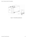
Installation of the air-intake adapter to the
underside of the RV
Locate a suitable location to mount the air-intake adapter.
Drill a 2” hole through the floor. Insert the adapter from
underneath and use 3 screws to secure against floor. The
air entrance of the air-intake assembly shall be guarded or
shielded to exclude rain, snow and debris. Use a #32 gear
clamp to attach the tubing to this adapter. Ensure the run
of tubing is as short as possible to facilitate air flow. See
figure 3-1.
Installation of the air-intake adapter to the side o
f
the RV
Locate a suitable location to mount the air-intake adapter.
Drill a 2” hole through the side wall (minimum ¼”,
maximum 2” wall thickness). Insert the adapter and use 3
screws to mount against side wall. Use a #32 gear clamp
to attach the tubing to this adapter. Ensure the run o
f
tubing is as short as possible to facilitate air flow. See
figure 3-1.
6 Secure both ends of the air-intake tubing with properly
sized hose clamps to prevent air leaks.
7 Make sure the air-intake and exhaust hoses have no leaks
and are not touching each other.
8 Protect the air-intake entrance from water and dirt with a
guard or shield.
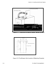
9 On a yacht, make sure the thru hull is at least 30” above
the waterline and the exhaust must be goose-necked, see
Figure 3-3: The Exhaust Goose Neck Configuration.
International Thermal Research 3-5