


Section 3, Installing the Exhaust System
• Use an ITR-manufactured muffler with a straight-through
design. No other muffler is acceptable.
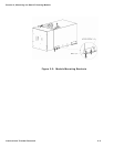
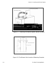
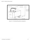
• Exhaust outlet is on the top or bottom (model dependant) of
the Oasis™ Heating Module, towards the back.
The exhaust and outlet are HOT and the surrounding areas
must be thermally shielded and protected from the hot
surfaces and heat build-up by insulation. Nothing can come
into inadvertent contact with any part of the exhaust system.
! DANGER
• Exhaust must have a minimum of 3” (7.6 cm) clearance from
all surfaces.
• Ensure that the exhaust cannot be plugged or restricted.
• The exhaust fitting on the Oasis™ Heating Module is
2.0” O.D. and the exhaust pipe used must have a minimum of
2.0” I.D. throughout its length.
• All exhaust elbows must be of a large radius design.
• The exhaust must be supported a minimum of every 3’ of its
installed length.
• The exhaust and Oasis™ Heating Module connection point
must use appropriate clamps and sealing compound to ensure
that the connections are tight and leak free. The Oasis™
Heating Module exhaust outlet pipe and the exhaust pipe
itself must not be distorted or damaged during this process.
• When the Oasis™ Heating Module is running the connection
points and the system must be checked for leaks and any
found must be corrected. Periodically, check the exhaust
fittings, connections, exhaust tube, and insulation for leaks
and integrity and correct if required.
• Appropriate exhaust insulation must be used to cover the
entire length of any interior exhaust run.
• Solid stainless steel exhaust tubing or approved exhaust
tubing is recommended but an approved stainless steel
flexible exhaust tubing can also be used. If flexible exhaust
tubing is used, the exhaust tubing must be inspected
regularly for leaks and deterioration as this type of exhaust
does not have the life expectancy of solid tubing. Stepped
International Thermal Research 3-3