


LOW VOLTAGE CONTROL WIRING
On-Off Controls
Controls are available from NORTEC as
accessories. If controls were not ordered with
humidifier, they must be purchased supplied by others.
The following information is relevant to all controls,
factory supplied or otherwise.
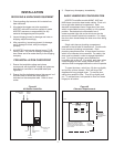
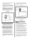
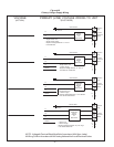
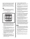
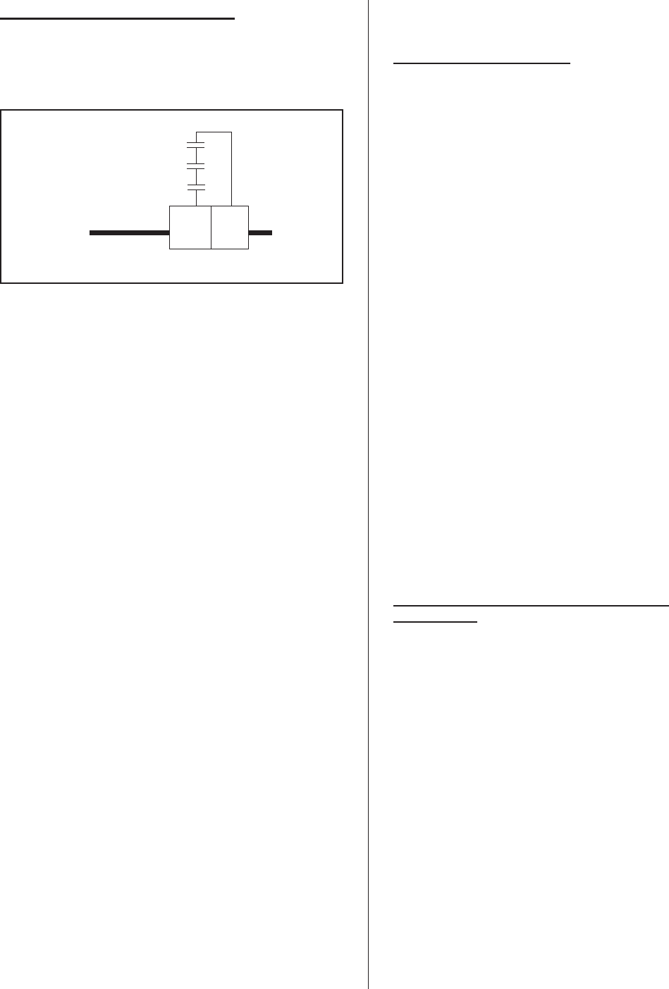
A, B and C (described below) are to be wired in
series (only one path for current) across terminals 8
and 10 on the low voltage control terminal strip, or
replaced with a jumper wire for constant operation.
Caution: this is the “hot” wire from the 24V control
transformer; it will blow the 3A fuse if any control field
wiring touches ground metal.
A - Wall or Duct Mounted Control On/Off
Humidistat: Wired to make on drop in humidity, break
on rise to setpoint. Set to desired % RH. Can be a
make/break set of contacts from a Building Automation
System.
B - Duct Mounted Safety High Limit On/Off
Humidistat (if used): Wired to make on drop in
humidity, break on rise to safety setpoint. Set to
approximately 85% RH as a safety to help prevent
saturation and wetting in the duct.
C - Duct Mounted Safety Air-Proving On/Off
Switch (if used): Wired to make when sensing air
flow, break when no air flow. Used as a safety to
prevent saturation when no air flow.
1. NORTEC offers various versions of A, B and C to
suit each application. In general, A is essential,
whereas B and C are highly recommended in
ducted applications.
2. Field wiring from humidistat to humidifier and
between devices should be 18 AWG or heavier
and kept as short as possible.
3. Low voltage control terminal strips are provided in
the electrical compartment. Internal sides are
factory wired. External sides are to be field wired.
4. Each humidifier is supplied with a wiring diagram
inside.
CONTROL INSTALLATION
1. Mount any wall humidistat (control or high limit)
over standard electrical box at height similar to
typical thermostat. Any wall humidistat should
be in location representative of overall space
being humidified and not in path of blower pack or
air supply grille. Do not mount on a outside wall
where temperature fluctuation can affect control
response.
2. Mount duct humidistat in location representative
of overall air humidity, usually return duct. Do not
mount it directly in front of steam distributor or in
turbulent or mixing zone. Mount it where air’s
humidity and temperature are uniform and
representative of spaces being humidified.
3. Mount duct high limit humidistat downstream of
steam distributors far enough that, under normal
humidity and air flow conditions, steam will have
been fully absorbed (typically at least 10 feet). It
must be located to sense high humidity only when
uniform and representative air is over-humidified
or approaching saturation.
4. Mount duct air-proving switch so that it is able to
sense air flow or lack of it. Wire it to make when
air flow is sensed and break when air flow fails.
5. Check operation of all on/off controls before
starting humidifier.
6. Calibration of controls (on/off or modulation) in the
field may be necessary due to shipping and
handling. Verify humidistat accuracy before
commissioning system.
OPTIONAL MODULATION (CONTINUOUS
CONTROLS)
1. Read on/off controls section first since it is
necessary to all control systems.
2. Virtually any modulation (continuous control)
external hardware by others (as long as it has
%RH setpoint circuitry) may be interfaced with
pre-specified factory-configured NHMC/NHP
Series pc board via the control terminal strip. The
NHB can be used with on-off control only. Use
shielded cables for modulation circuits.
3. Modulation (continuous control) by others for use
with NHMC/NHP Series humidifiers involves one
of several control wiring diagrams. In all cases,
modulating signal interfaces through control
terminal strip to main pc board inside humidifier.
4. The modulation signal must increase from
minimum toward maximum as sensed RH (actual
RH) drops below desired RH (%RH setpoint). In
response, humidifier’s steam output will increase
from minimum toward maximum. When
humidifier’s steam output (lbs/hr) matches
humidification load (lbs/hr), modulation signal will
stabilize.
-5-
A
B
C
810
EXTERNAL
INTERNAL
Figure #9
External Wiring of On/Off Controls