


safety thermostat to turn off the humidifier if the
blower pack gets overheated. Control thermostat,
mounted on the steam distributor, starts the fan
when steam is generated. When supply voltage
differs from voltage required to run blower motor,
blower pack will contain a proper transformer. All
blower packs provide intake air filters.
For installation details about the blower pack,
please refer to the blower pack installation manual
located in the blower pack box (Form #XX-239).
STEAM DISTRIBUTORS
1. Steam distributors are used in ducts or air
handling units, and are made of stainless steel.
2. Steam distributors can be in vertical or downflow
applications.
3. Proper location should consider: air temperature,
relative humidity before the distributor, air velocity,
dimensions of the location, amount of steam
introduced into the duct, downstream obstructions,
and surfaces vulnerable.
4. For installation details, please refer to steam
distributor installation manual located in the
distributor box (Form #XX-231).
5. For calculating absorption distances, refer to
H.E.L.P. Software or steam distribution and
absorption distances engineering manul (Form
#XX-232).
PLUMBING
All water supply and drain line connections
should be installed in accordance with local
plumbing codes.
WATER SUPPLY LINE
1. Humidifier is intended to operate on potable (cold)
tap water.
2. If the raw water is very hard, NORTEC can
provide longer cylinder life on softened water.
However, softened water is more conductive and
more corrosive. Some hardware and/or software
changes may be required, at time of order or in the
field. Consult factory.
3. If RO or DI is available, blending may increase
cylinder life. Consult factory.
4. DO NOT use a hot water supply to humidifier.
Minerals will adhere more easily to surfaces and
the fill valve’s small flow regulating orifice and
could become plugged.
5. Standard fill valves are sized for water pressure
ranging from 30 to 80 psig (ideally 55 to 60 psig).
For other pressures, consult factory. This
pressure should be measured at the humidifier if
the water pressure is suspect.
6. ALWAYS supply and install a shut off valve in the
water supply line dedicated to the humidifier to
facilitate servicing. Use ½" OD copper to within 4
feet of the humidifier. Reduce copper to 3/8" OD
and connect to the factory-supplied 3/8" olive
compression fitting under the humidifier.
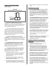
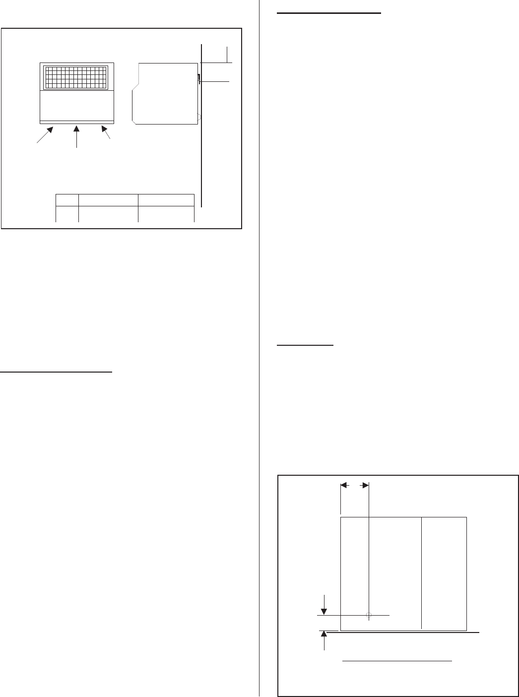
DRAIN LINE
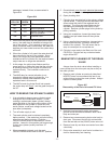
1. Humidifier is equipped with a 7/8" O.D. unthreaded
drain outlet on underside of drain canal on bottom
of the humidifier (see Figure #6). A field-supplied
funnel (see Figure #7) is recommended. It will
prevent backup in the drain pan and in the cylinder
due to partially blocked or badly installed drain
lines. This prevents rusting of the drain pan and
arcing due to over-concentration. The drain canal
-3-
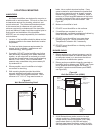
005-030
3.2" (8.0cm)
050-100
3.2" (8.0cm)
A
Front
W
a
ll
Side
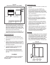
Steam
Condensate
A
Power and control
wiring from humidifier
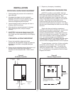
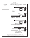
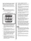
Figure #5
Remote Mounted Blower Packs (RMBP)
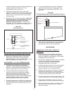
Bottom View
Wall
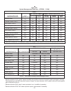
B
A
Model
005-030
050-100
150-200 Left
150-200 Right
B in.(mm)
19.6
(
498
)
Ain.(mm)
1.0(25)
2.2(55)
2.2(55)
2.2(55)
6.2(158)
6.2(158)
5.0(127)
Figure #6
Drain Line Connection