LOCATION & MOUNTING
HUMIDIFIERS
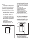
NH Series humidifiers are designed to mount on a
suitable wall or vertical surface. Do not sit on floor due
to clearances required for plumbing, electrical, and
control entrances. The clearance dimensions shown
in this manual are for reference only and are the
minimum required for maintenance of the humidifier.
Local and National Codes should be consulted prior to
final location and installation of the humidifier.
NORTEC can not accept responsibility for installation
code violations.
1. Location of the humidifier should be below and as
close as possible to the steam distributor location
as possible.
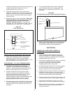
2. For front and side clearance requirements (for
access during installation, maintenance and
troubleshooting), see Figure #2.
3. If possible, DO NOT locate humidifier any further
than absolutely necessary from steam distributor
location, as net output will be reduced as a result
of heat loss through steam hose (see Engineering
Manual, Form -163D). Also, increased static
pressure may necessitate using an accessory fill
cup extension kit.
4. Where possible, mount humidifier at a height
convenient for servicing.
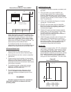
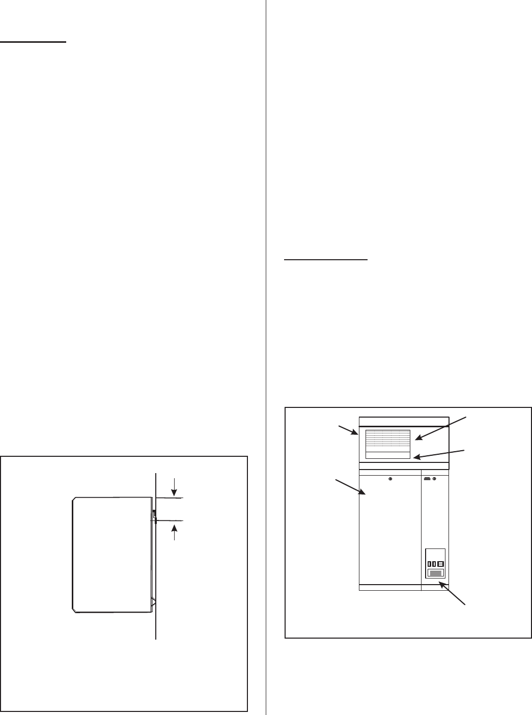
5. Wall mounting bracket provided should be
securely attached horizontally and open edge
upwards, using field-supplied fasteners. Use a
minimum of 3 - #12 x 3" long wood screws, or
better, into a vertical structural surface. If any
spacer material is used between the bracket and
the structural material such as drywall, increase
fastener length accordingly. In addition, install a
minimum of 2 field supplied fasteners in the holes
provided in the back of the unit to prevent the unit
from being bumped off the wall bracket. See
Figure #3.
6. Make sure humidifier is level.
7. DO NOT mount humidifier on hot surfaces.
8. If humidifiers are mounted on roof, a
thermostatically ventilated weatherproof cabinet by
others should be used. Consult factory.
9. DO NOT mount humidifiers in an area where
freezing may occur. Use an accessory Low
Temperature Protection Kit, if necessary.
10. DO NOT mount humidifiers on vibrating surface.
Consult factory.
BLOWER PACKS
1. Blower packs are an optional accessory used to
directly distribute steam to localized areas (such
as computer rooms) or in structures that do not
have a built-in air distribution system.
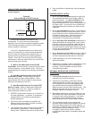
2. Blower packs are available integrally-mounted on
humidifier (built-on blower pack, BOBP, see Figure
#4) or detached and field-piped and wired to
humidifier (remote mounted blower pack RMBP,
see Figure #5).
3. All NH Series blower packs consist of a steel
cabinet containing: blower/motor powered by
voltage directly from the humidifier, fuse, relay,
speed select switch (in NH-050 and larger),
stainless steel steam distributor, supply air grille
with adjustable louvers, and built-in manual reset
-2-
Power And
Control
Wirin
g
Optional
Built-On
Blower Pack
Single
Circuit
Humidifier
Built-In
Supply Air
Grille
Built-In Steam
Distributor
Figure #4
Built On Blower Pack (BOBP)
005-030
7.7 (19.6cm)
050-200
7.7 (19.6cm)A
WALL
FASTEN WALL BRACKET
(FACTORYSUPPLIED) TO
WALL USING ANCHORBOLTS
(3) SUPPLIED BYOTHERS
A
7.7”
(19.6 cm)
Fasten wall bracket
(Factory supplied) to
wall using field supplied
fasteners.
Wall
Figure #3
Wall Bracket Mounting Detail


