


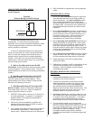
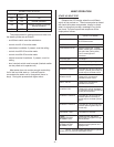
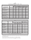
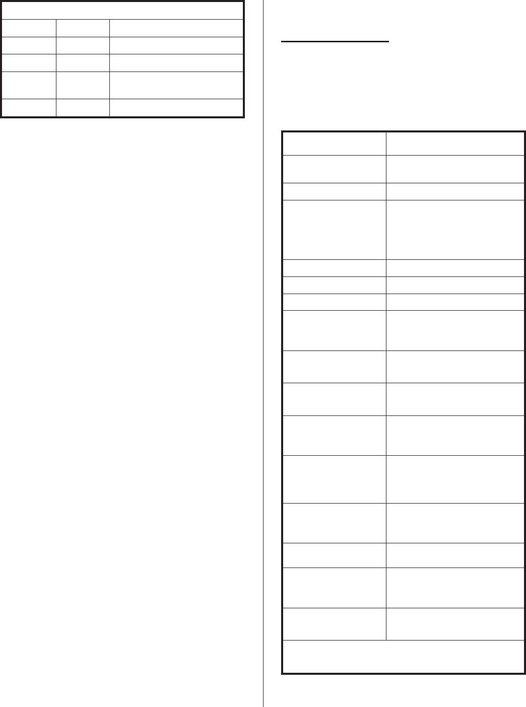
SIGNAL LIGHT STATUS
YELLOW GREEN
OFF OFF Off
OFF ON Normal operation
ON ON Replace cylinder or normal
startup operation
ON OFF Operation fault
The prerequisites for getting power and water into
the steam cylinder are as follows:
-
on/off/drain switch must be switched on
-
control circuit 8-10 must be made
-
modulation humidistat, if present, must be calling
-
control circuit 82-83 must be made
-
control circuit 84-85 must be made
-
cabinet mounted humidistat, if present, must be
calling
- door interlock switch must be made (interlock switch
can be pulled out to operate unit)
Most water does not contain enough conductivity
for full boil on initial start-up. Units will need to
concentrate the water over a time period (hours to
days). During this process both lights are on.
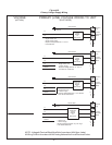
NHMC OPERATION
START-UP SELF TEST
Observe the LCD display when the on/off/drain
switch is first pushed on. The microcomputer pc board
will check the system components, display in words
what it is doing and provide a message if any faults
are found. The start-up self-test sequence will be
displayed as follows:
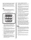
LCD EXPLANATION/COMMENTS
(WHAT YOU READ)
CONDAIRMATIC MC Note the V number. It tells you
the EPROM version.
NORTEC V2...
CONDAIRMATIC MC Note the model type. Ensure
NHMC (model type) compatibility
with spec label (name plate).
Can be reconfigured if
necessary.
SYSTEM TEST Test begins.
LAMP GREEN Observe green signal light on
LAMP YELLOW Observe yellow signal light on
CONTACT RELAY 1 Provides 24 VAC to 61-20 and
external optional yellow lamp at
control strip to simulate a fault.
DRAIN VALVE Observe 24 volt solenoid
activated on drain valve.
INLET VALVE Observe 24 volt solenoid
activated on fill valve.
CONTACTOR Observe 24 volt coil activated
on contactor OR fan activated on
blower pack if present.
CONTACT RELAY 2 Provides 24 VAC to 63-36 and
external optional red lamp at
control strip to simulate cylinder
spent.
CONTACT RELAY 3 Provides 24 VAC to 62-40 and
external optional green lamp at
control strip.
INTERNAL TEST Completion of self test.
LAMP
GREEN-YELLOW
INTERNAL TEST
Observe green and yellow
lamps pulse on together as sign
that all passed.
STEAM OUTPUT
INTERNAL TEST
Begins normal operation and
displays lbs/hr.
NOTE: If cylinder water reaches the full cylinder
sensor, the LCD will read “MAXIMAL LEVEL”.
-8-