


high water sensor board has a primary voltage side.
One leg connects to the primary leg; one leg connects
to the short sensor pin in the top of the cylinder. A
potential, somewhat less than primary, is picked up by
the sensor at high water level, which “makes” the
red/black circuit on the low voltage side. This creates
a resistive loop across terminals 2-4 on the electronics
which stops the fill valve until water boils down below
the sensor pin.
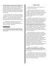
Back at the electronics, the contactor receives its
“hot leg” from terminal 12. The fill receives its “hot leg”
from terminal 14. The drain receives its “hot leg” from
terminal 16. Unlike the contactor and fill, the drain
gets its “ground leg” directly from the transformer. It
does not depend on the air proving switch to activate.
The yellow and green status lamps are LED’s.
Polarity is important. Terminal 26 is positive dc
supply. Terminal 22 and 24 are switched dc grounds
for yellow and green respectively.
BLOWER PACKS
An optional blower pack (BP), if present, gets its
primary voltage from inside the humidifier. This way,
only one external power source has to be connected to
the equipment.
TERMS USED
RATED AMPS: Refers to amps listed on the
humidifier specification label.
SHORT CYCLING: When the ‘on time’ of the
humidifier is less than ten minutes upon a call for
humidity. To correct short cycling, all humidifiers have
a capacity adjustment which allows the output of the
humidifier to be reduced as low as 20% of rated
output, thus extending the ‘on time’ required to
maintain output.
FOAMING: The phenomenon which can occur in
water when the impurities, already in the water, reach
an excess concentration as result of boiling away pure
water and the continued boiling action agitating the
contained water. The humidifier electronics are
designed to prevent this occurrence although in
extreme cases water will foam with little concentration,
making it necessary to have the drain time of the
water, contained in the cylinder, increased. Foaming
is normally caused by short cycling, a restricted drain,
or back pressure. The foam, generated in these
instances, is conductive and may lead to a false full
cylinder indication if the level of the foam approaches
the top of the cylinder.
BACK PRESSURE: Restriction of steam flow
caused by long steam runs, improperly sloped steam
lines, elbows changing the direction of the steam flow
from horizontal to vertical without a drain leg, any
plumbing detail allowing the accumulation of
condensate, undersized steam line, improper steam
distributor, downward air flow onto the distributor
creating excess static pressure at the steam outlets or
high static pressure ducts (not probable). To
overcome excess static pressure in the duct, a fill cup
extension kit should be used. In downflow
applications, a downflow distributor should be used but
in some cases the fill cup extension will also be
required.
RESET UNIT (HUMIDIFIER): To reset the
humidifier, the on/off/drain switch at the front of the
humidifier should be switched to the off position for a
minimum of five seconds and then switched back to
the on position.
MONITORED LEG: Refers to the primary wire, to
the cylinder, which loops through the current sensing
device on the main pcb. This wire is terminated at the
red cylinder plug at the cylinder. Units with six primary
wires to the cylinder will monitor only one of the two
wires, terminating with red plugs.
-22-