


14
GAS-FIRED BOILER Boiler Manual
PART 5: BOILER PIPING
(CONTINUED)
diagrams, the space heating system is
isolated from the boiler loop by the
primary/secondary connection.
2. Size the piping and components in the space
heating system using recognized design
methods.
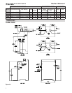
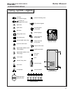
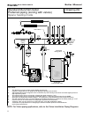
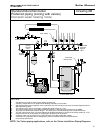
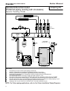
G. HYDRONIC PIPING WITH CIRCULATORS,
ZONE VALVES AND MULTIPLE BOILERS
The Munchkin Boiler is designed to function in a
closed loop 15 PSI System. A factory installed
water pressure switch will ensure that you have
adequate pressure in the system. The Munchkin
Boiler will not operate without a minimum of 10
PSI water pressure. This assures you that if the
system does have leak, the Munchkin Boiler will
lock out (PRO on the display) before it damages
the Stainless Steel Heat Exchanger. We have also
included a Temperature and Pressure gauge
which allows the user to monitor the system
pressure and outlet temperature from the
Munchkin Boiler. It is important to note that the
Munchkin Boiler has a minimal amount of
pressure drop and must be calculated when
sizing the circulators. Each Munchkin Boiler
installation must have an Air Elimination device
that will remove air from the system. Install the
Munchkin Boiler so the gas ignition system
components are protected from water (dripping,
spraying, etc.) allowing clearance for basic
service of circulator replacement, valves and
other. Observe minimum 1” clearance around all
un-insulated hot water pipes when openings
around pipes are not protected by non-
combustible materials. On a Munchkin Boiler
installed above radiation level, some states and
local codes require a low water cut off device at
the time of installation (See Part C this section). If
the Munchkin Boiler supplies hot water to heating
coils in air handler units, flow control valves or
other devices must be installed to prevent gravity
circulation of heater water in the coils during the
cooling cycle. Chilled Water Medium must be
piped in parallel with the heater. Freeze Protection
for new or existing systems must use glycol that
is specifically formulated for this purpose. It will
include inhibitors that will prevent the glycol from
attacking the metallic system components. Make
certain that the system fluid is checked for the
correct glycol concentration and inhibitor level.
The system should be tested at least once a year
and as recommend by the producer of the glycol
solution. Allowance should be made for the
expansion of the glycol solution in the system
piping. Example 50% by volume solution
expands 4.8% in volume for the temperature
increase from 32 F to 180 F, while water expands
3% with the same temperature rise.
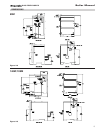
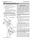
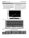
Basic steps are listed below, with Illustration,
which will guide you through the installation of
the Munchkin.
1. Connect the system return marked “Heater In”.
2. Connect the system supply marked “Heater Out”.
3. Install Purge and Balance Valve or shut off
valve and drain on system return to purge air
out of each zone.
4. Install a Back Flow preventor on the Cold Feed
Make-Up Water line.
5. Install a Pressure Reducing Valve on the Cold
Feed Make-Up Water line, (15 PSI nominal on
the system return). Check Temperature and
Pressure Gauge which should read minimum
pressure of 12 PSI.
6. Install a circulator as shown in piping details
(this section). Make sure the circulator is
properly sized for the system and friction loss.
7. Install an Expansion Tank on the system
supply. Consult the tank manufacturer’s
instruction for specific information relating to
expansion tank installation. Size the expansion
tank for the required system volume and
capacity.
8. Install an Air Elimination Device on the system
supply.
9. Install a drain valve at the lowest point of the
system. Note: The Munchkin Boiler can not be
drained completely of water without purging
the unit with an air pressure 15 PSI.
CAUTION
The Munchkin Boiler should not be operated as
a potable Hot Water Heater. It should not be
used as a direct Hot Water Heating Device.