


CDVSC7 & CDV7 Series Gas Fireplace
40
69D3011
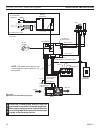
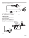
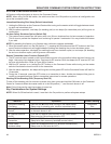
Figure 58 -
BLOT Blower Wiring Diagram
BLACKBLACKWHITE
GREEN
BLACK
BLACKWHITE
Receptacle
Junction
Box
120VAC
Speed Control
FP2675
BLOT blower wiring
FP675
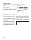
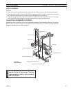
Before installing the blower, wire the receptacle into an
electrical circuit. This should be done before framing the
fireplace. Wire with minimum 60° C wire in accordance
with prevailing codes.
1. This must be done before framing the fireplace. When
installing the FK-1 blower, a wall switch control must
be installed to control the blower.
. The fireplace power supply is wired through the blower
wall switch and then brought to the fireplace junction
box.
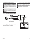
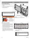
3. The jumper clip on the plug receptacle must be re-
moved. Figure 59. Use needlenose pliers to break off
the jumper clip.
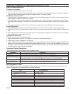
Junction Box
Blower
Wall Switch
Black (live)
Green (ground)
White (neutral)
Red
Black
FK-12 Blower
Plug into switch outlet
FP2676
FK12 wiring
Jumper clip on plug
receptacle must be
removed on power side to
make outlet switchable
Figure 59 -
FK-12 Blower wiring Diagram
FP676