


CDVSC7 & CDV7 Series Gas Fireplace
69D3011
17
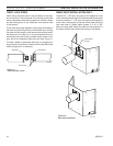
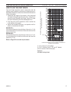
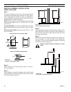
The Vent Graph should be read in conjunction with the
following vent installation instructions to determine the re-
lationship between the vertical and horizontal dimensions
of the vent system.
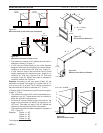
1. Determine the height of the center of the horizontal
vent pipe exiting through the outer wall. Using this di-
mension on the Sidewall Vent Graph, Figure 13, locate
the point intersecting with the slanted graph line.
. From the point of this intersection, draw a vertical line
to the bottom of the graph.
3. Select the indicated dimension, and position the fire-
place in accordance with same.
If the vertical dimension from the floor of the unit is 11’ (3.4
m) the horizontal run to the face of the outer wall must not
exceed 14’ (4.3 m).
If the vertical dimension from the floor of the unit is 7’ (.1
m), the horizontal run to the face of the outer wall must not
exceed 8’ (.4 m).
Page 24
40
38
36
34
32
30
28
26
24
22
20
18
16
14
12
10
8
6
4
2
2 4 6 8 10 12 14 16 18 20
eg: A
FP2291
vent graph
X
Vertical Dimension from the Floor of Unit to the Center of
the Horizontal Vent Pipe
Horizontal Dimension From the Outside of Termination to
the Back of the Fireplace
Figure 13 -
Side Wall Venting Graph
X = " minimum for 33" Model
X = 5Z\v" minimum for 36", 4" and 47" Models
(Floor to center of horizontal pipe)