


CDVSC7 & CDV7 Series Gas Fireplace
69D3011
31
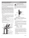
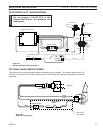
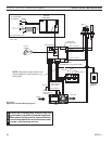
Figure 45 -
Remote Wall Switch Wiring Diagram
#1 #2#3 #4 #5 #6 7#
Electronic Valve
GRAY #7
RED #2
RED #2
BLACK #4
GREEN #6
BLUE #1
BLUE
YELLOW
YELLOW
WHITE #3
MAGENTA #5
15’ Wall Switch Wire
BLACK
WHITE
Switch
RS
OFF
ON
Transformer
Secondary
24V
WHITE
WHITE
GREEN
BLACK
BLACK
Primary - 120V
To Junction Box
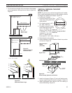
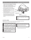
Pilot Assembly
Sense
Ignition Module (Synetek)
Spark
FP2295
electronic wiring diagram
HI
LO
EV1 EV2
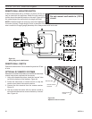
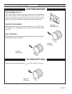
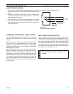
The junction box for the fan/blower systems has been factory installed. This system requires that 110-
10 VAC to be wired to the factory installed junction box before the fireplace is permanently installed.
Figure 46
Black
Black
Green
Black
Black
White
Thermostatic
Switch
Receptacle
Junction Box
120V AC
FP2296
blower wiring
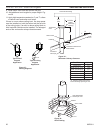
Speed Control
Thermostatic
Control Blower
FP96
Figure 46 -
Blower Wiring Diagram