[ VII Control ]
- 115 -
HWE09120 GB
[3] Operation Flow Chart
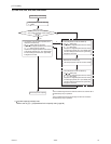
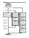
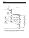
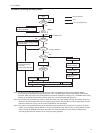
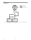
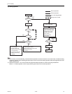
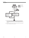
1. Mode determination flowchart
(1) Indoor unit (cooling, heating, dry, fan mode)
*Note 1. Indoor unit LEV fully closed : Opening 41.
*Note 2. The system may go into the error mode on either the indoor unit or the outdoor unit side. If some of the indoor units are
experiencing a problem (except water leakage), only those indoor units that are experiencing the problems will stop.
If the outdoor unit is experiencing a problem, all connected indoor units will stop.
*Note 3. The operation will be prohibited when the set cooling/heating mode is different from that of the outdoor unit.
Start
Remote controller
display lit off
Error mode
Error stop
Error display
Self-holding of
protection function
Error command
to outdoor unit
Indoor unit LEV
fully closed.
Refer to 2-(1)
Cooling operation.
Refer to 2-(2)
Heating operation.
Refer to 2-(3)
for dry operation.
ProhibitionProhibitionProhibition
Dry display
Heating displayCooling display
Dry mode
Heating mode
Fan mode
Fan display
Fan operations
Operation mode
Cooling mode
Operation command to outdoor unit (to 2 )
Prohibition
"Blinking display on
the remote controller"
FAN stop
Breaker
turned on
Operation SW
turned on
Auxiliary heater
ON
Drain pump
ON
3-minute
drain pump ON
NO
NO
NO
NO
NO
NO NO NO
*Note 1
*Note 2
*Note 1
*Note 3 *Note 3 *Note 3
1. Protection function
self-holding cancelled.
2. Indoor unit LEV fully closed.
1. Auxiliary heater OFF
2. Low fan speed for
1 minute
YES
YES
YES
YES
YES YES YES
YES
Normal operation
Error
Unit in the stopped state
From outdoor unit
1


