


24
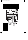
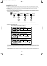
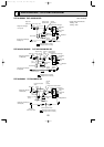
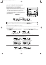
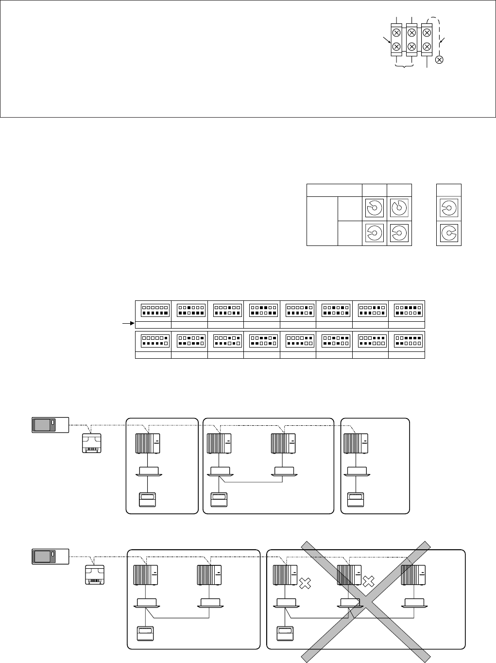
8-4-3. Regulations in address settings
In case of multiple grouping system, M-NET and refrigerant address settings should be done as explained in the above sec-
tion. Set the lowest number in the group for the outdoor unit whose refrigerant address is “00” as its M-NET address.
w Refrigerant addresses can be overlapped if they are in the different group.
w In group B, M-NET address of the outdoor unit whose refrigerant address is “00” is not set to the minimum in the group. As
“03” is right for this situation, the setting is wrong. Taking group A as a good sample, set the minimum M-NET address in
the group for the outdoor unit whose refrigerant address is “00”.
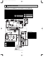
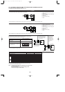
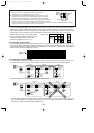
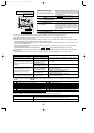
8-4-1. M-NET address setting
In A-control models, M-NET address and refrigerant address should be set only for the outdoor unit. Similar to CITY MULTI
series, there is no need to set the address of outdoor unit and remote controller. To construct a central control system, the
setting of M-NET address should be conducted only upon the outdoor unit. The setting range should be 1 to 50 (the same as
that of the indoor unit in CITY MULTI system), and the address number should be consecutively set in a same group.
Address number can be set by using rotary switches
(SW11 for ones digit and SW12 for tens digit), which
is located on the M-NET board of outdoor unit.
(Initial setting: all addresses are set to “0”.)
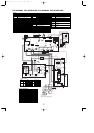
8-4-2. Refrigerant address setting
In case of multiple grouping system (multiple refrigerant circuits in one group), indoor units should be connected by remote
controller wiring (TB5) and the refrigerant address needs to be set. Leave the refrigerant addresses to “00” if the group set-
ting is not conducted. Set the refrigerant address by using DIP SW1-3 to -6 on the outdoor controller board. [Initial setting: all
switches are OFF. (All refrigerant addresses are “00”.)]
1
2
3
4
5
6
7
8
9
0
1
2
3
4
5
6
7
8
9
0
1
2
3
4
5
6
7
8
9
0
1
2
3
4
5
6
7
8
9
0
1
2
3
4
5
6
7
8
9
0
1
2
3
4
5
6
7
8
9
0
12
~
50
M-NET Address No.
<Setting example>
Switching
setting
SW11
ones
digit
SW12
tens
digit
OFF
ON
1
2
3
4
5
6
1
2
3
4
5
6
1
2
3
4
5
6
1
2
3
4
5
6
1
2
3
4
5
6
1
2
3
4
5
6
1
2
3
4
5
6
1
2
3
4
5
6
1
2
3
4
5
6
1
2
3
4
5
6
1
2
3
4
5
6
1
2
3
4
5
6
1
2
3
4
5
6
1
2
3
4
5
6
1
2
3
4
5
6
1
2
3
4
5
6
0
Refrigerant
address
OFF
ON
8
OFF
ON
1
OFF
ON
9
OFF
ON
10
OFF
ON
11
OFF
ON
12
OFF
ON
13
OFF
ON
14
OFF
ON
15
OFF
ON
2
OFF
ON
3
OFF
ON
4
OFF
ON
5
OFF
ON
6
OFF
ON
7
System
controller
A-control
remote
controller
Group A Group B Group C
A-control
remote
controller
TB5
A-control
remote
controller
Refrigerant
address 00
M-NET
address 01
Refrigerant
address 00
M-NET
address 02
Refrigerant
address 01
M-NET
address 03
Refrigerant
address 00
M-NET
address 04
Power
supply
unit for
transmission
wire
A-control
remote
controller
A-control
remote
controller
TB5
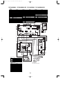
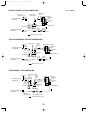
Group A Group B
Refrigerant
address 00
M-NET
address 01
Refrigerant
address 01
M-NET
address 02
Refrigerant
address 00
M-NET
address 04
Refrigerant
address 01
M-NET
address 03
Refrigerant
address 02
M-NET
address 05
System
controller
Power
supply
unit for
transmission
wire
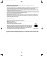
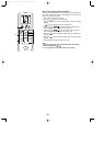
● M-NET wiring
(1) Use 2-core x 1.25mm
2
[AWG16] shield wire for electric wires.
(Excluding the case connecting to system controller.)
(2) Connect the wire to the M-NET terminal block. Connect one core of the
transmission wire (non-polar) to A terminal and the other to B. Peel the
shield wire, twist the shield part to a string and connect it to S terminal.
(3) In the system which several outdoor units are being connected, the terminal
(A, B, S) on M-NET terminal block should be individually wired to the other
outdoor unit’s terminal, i.e. A to A, B to B and S to S. In this case, choose one of those outdoor units and drive a screw
to fix an ground wire on the plate as shown on the right figure.
Transmission
wire
Shield
part
M-NET
terminal
block
Ground
wire
ABS
OCH429--1.qxp 07.11.20 9:17 AM Page 24