


113
OPERATING PROCEDURE
PHOTOS
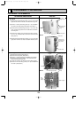
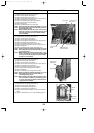
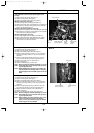
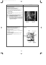
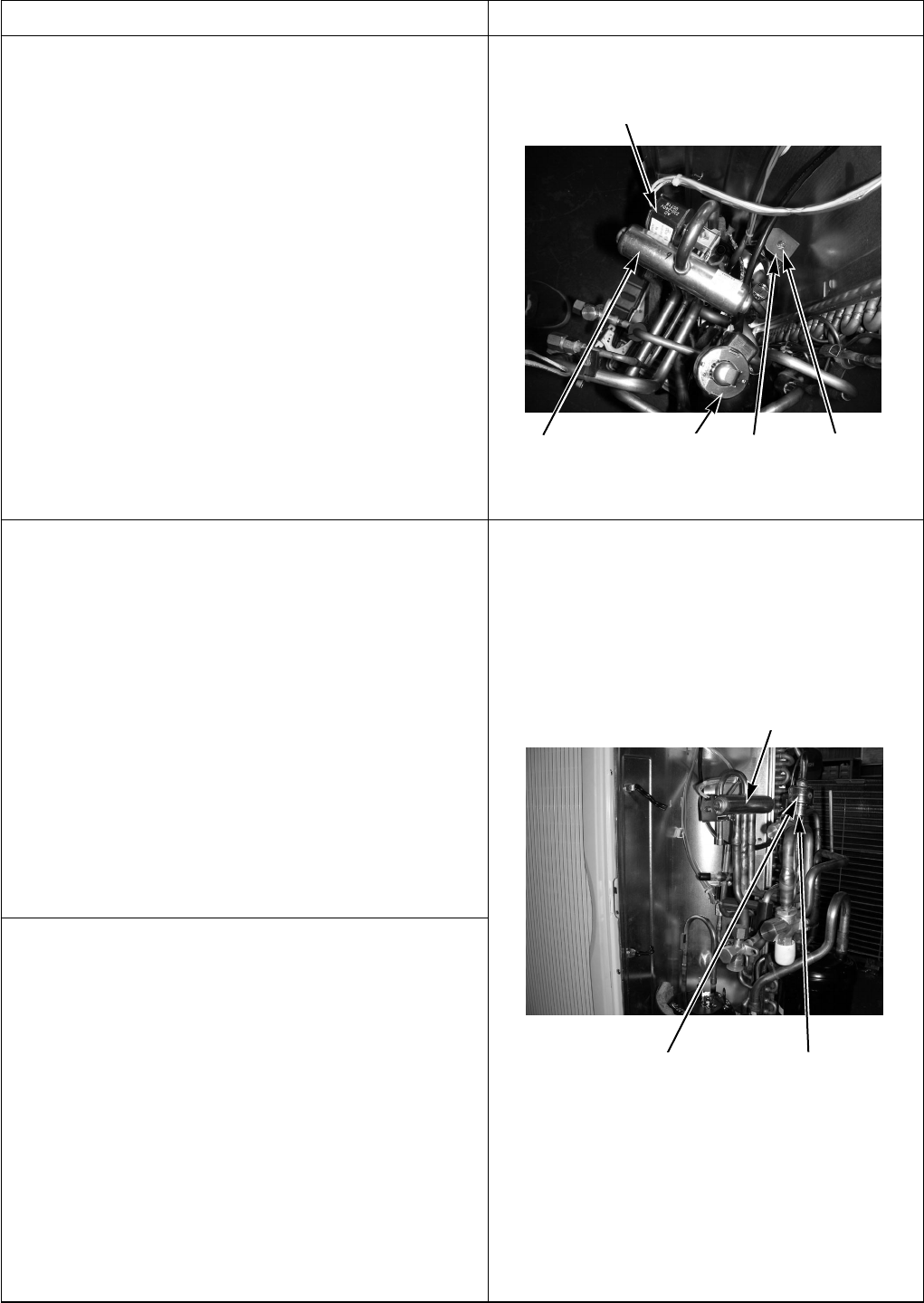
7. Removing the 4-way valve coil (21S4),
linear expansion valve coil (LEV-A) and bypass valve
coil (SV)
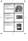
(1) Remove the service panel. (See figure 1.)
(2) Remove the top panel. (See figure 1.)
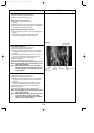
(3) Remove the electrical parts box. (See photo 3.)
[Removing the 4-way valve coil]
(4) Remove 4-way valve coil fixing screw (M4 ✕ 6).
(5) Remove the 4-way valve coil by sliding the coil toward you.
(6) Disconnect the connector 21S4 (green) on the controller
board in the electrical parts box.
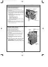
[Removing the linear expansion valve coil]
(4) Remove the linear expansion valve coil by sliding the coil upward.
(5) Disconnect the connectors, LEV-A (white),on the controller
circuit board in the electrical parts box.
[Removing the bypass valve coil]
(4) Remove the bypass valve coil fixing screw (M4 ✕ 6).
(5) Remove the bypass valve coil by sliding the coil upward.
(6) Disconnect the connector SV2 (blue) on the controller
circuit board in the electrical parts box.
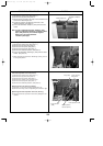
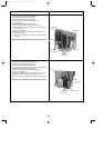
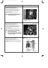
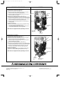
8. Removing the 4-way valve
(1) Remove the service panel. (See figure 1.)
(2) Remove the top panel. (See figure 1.)
(3) Remove the electrical parts box. (See photo 3.)
(4) Remove 3 valve bed fixing screws (4 ✕ 10), 4 ball valve
and stop valve fixing screws (5 ✕ 16), then remove the
valve bed.
(5) Remove 3 right side panel fixing screw (5 ✕ 10) in the
rear of the unit and then remove the right side panel.
(6) Remove the 4-way valve coil. (See photo 7.)
(7) Recover refrigerant.
(8) Remove the welded part of 4-way valve.
Note 1: Recover refrigerant without spreading it in the air.
Note 2: The welded part can be removed easily by remov-
ing the right side panel.
Note 3: When installing the 4-way valve, cover it with a wet
cloth to prevent it from heating (250˚F or more), then
braze the pipes so that the inside of pipes are not oxi-
dized.
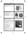
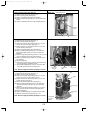
9. Removing the linear expansion valve
(1) Remove the service panel. (See figure 1.)
(2) Remove the top panel. (See figure 1.)
(3) Remove the electrical parts box. (See photo 3.)
(4) Remove 3 valve bed fixing screws (4 ✕ 10), 4 ball valve
and stop valve fixing screws (5 ✕ 16), then remove the
valve bed.
(5) Remove 3 right side panel fixing screw (5 ✕ 10) in the
rear of the unit and then remove the right side panel.
(6) Remove the linear expansion valve. (See photo 7.)
(7) Recover refrigerant.
(8) Remove the welded part of linear expansion valve.
Note 1: Recover refrigerant without spreading it in the air.
Note 2: The welded part can be removed easily by remov-
ing the right side panel.
Note 3: When installing the linear expansion valve, cover
it with a wet cloth to prevent it from heating
(250˚F or more), then braze the pipes so that the
inside of pip-es are not oxidized.
Photo 7
Photo 8
Bypass valve
coil fixing
screw
4-way
valve
4-way valve coil
Linear expansion
valve coil (LEV-A)
4-way valve
Bypass
valve
coil(SV)
Linear expansion
valve coil (LEV-A)
Linear expansion
valve
OCH429--4.qxp 07.11.20 9:20 AM Page 113